 International
 Singapore
 Malaysia
 Thailand
 Vietnam
Your shopping cart is empty!
 Board (CM4-IO-BASE-A)")
Getting Started Raspberry Pi Compute Module 4 Lite And Mini Base (A) Board (CM4-IO-BASE-A)
- Hussien Jawhar Sathik
- 16 Jun 2022
- Tutorial
- 1451
Introduction
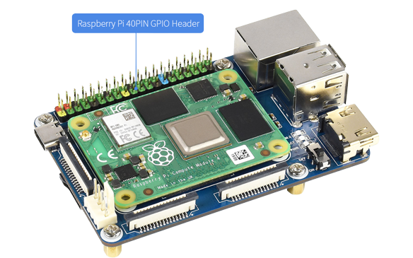
The Raspberry Pi Compute Module 4 (CM4) is a System on Module containing processor, memory, eMMC Flash and supporting power circuitry. This module represent a huge change for the Compute Module line. The biggest transformation being the move from the DDR2 SODIMM connector form factor to a high density connector on the bottom of the board. These modules allow a designer to leverage the Raspberry Pi hardware and software stack in their own custom design and form factors. In addition, these modules have extra IO interfaces over and above what is available on the Raspberry Pi boards, which opens up more option for the designer.
The board includes the same 1.5GHz quad-core 64-bit ARM Cortex-A72 on the Raspberry Pi 4 and is capable of 4k Video via dual HDMI interfaces. It has a single-lane PCI 2.0 express interface with dual MIPI DSI Display and CSI-2 camera interfaces. The board supports Gigabit Ethernet PHY with IEEE 1588 support and has 28 GPIO pins, with up to 6 × UART, 6 × I2C and 5 × SPI. This model has 1GB of LPDDR4-3200 SDRAM and no on-board Flash storage. That' about the CM4. Now let's look at the CM4-IO-BASE-A.
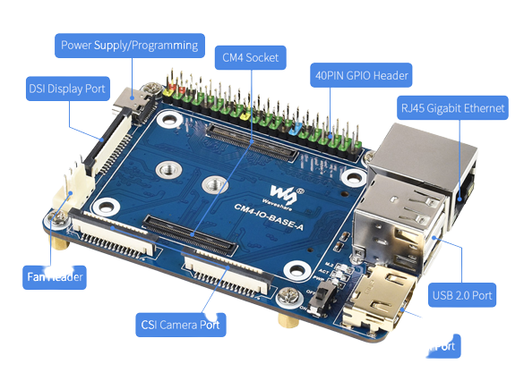
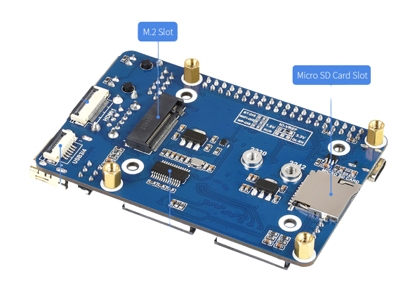
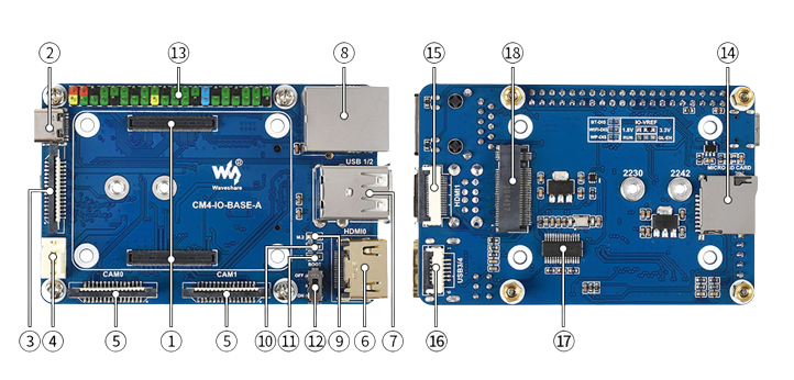
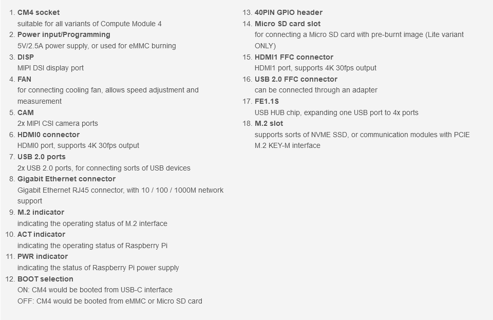
The CM4-IO-BASE-A board is a module which is suitable for evaluating the Raspberry Pi CM4 or integrating into end products. The following figures below explains more about the future of the board.
Video
Hardware Setup
Now we have seen the specification of both the compute module and base carrier board, let see how to setup the devices before we can power up for the first time. Since the compute module which i am using is the lite version and it does not comes with the onboard eMMC, we need to flash the OS on the SD card. This step is similar with the step we use to flash OS for other Raspberry Pi.
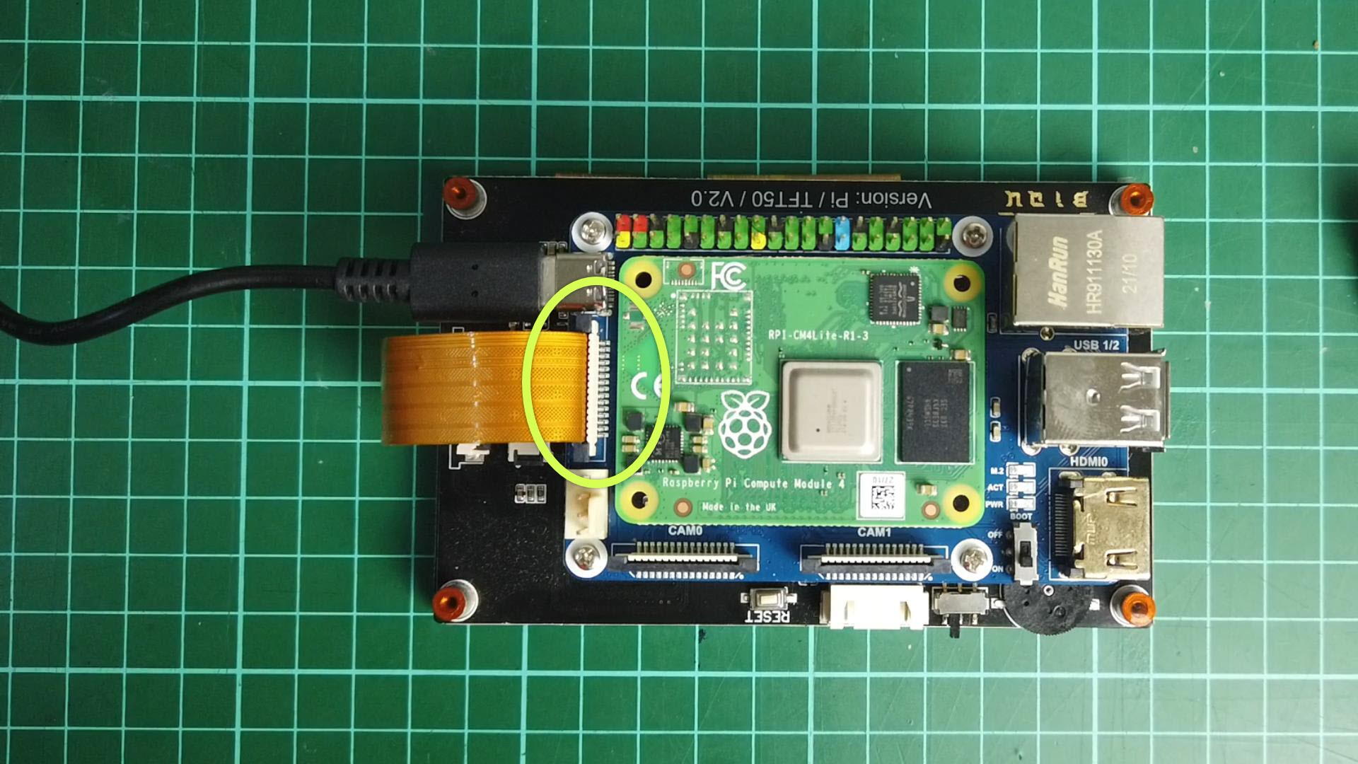
Once the SD card is flashed with the fresh OS, now we are ready to power up. But before that we need to make sure all the devices are connected together. The CM4 board is installed on the base board through the snap slot. Make sure to hear the snap sound when installing the the board. Next is to connect the board to the display panel. I have used the 5-inch 800x480 5 Points Touch Screen for Raspberry Pi from Biqu as the display. The connection between the board and the display is through the DISP Interface. And by default this input is disabled and need to be enabled in order to use this port. This need to be done after powering up. Using the HDMI port however has no issue since it is enabled by default. The figure below shows the setup of the hardware.
Powering Up The First Time
Powering up the first time is pretty much straight forward as there is no any special requirement. Just make sure that the SD card is installed and also the BOOT selection switch is set to OFF. Once power up, the power and activity led on the carrier board will start to illuminate, but the display stay blank.
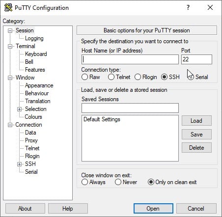
Next we need enable the DISP port. For this i have used the putty application and try to access the raspberry. The putty window screen will look like below:
Once we are able to access the Raspberry Pi , we can now key in the following command:
wget https://www.waveshare.net/w/upload/7/75/CM4_dt_blob_Source.zip
 unzip -o  CM4_dt_blob_Source.zip -d ./CM4_dt_blob_Source
 sudo chmod 777 -R CM4_dt_blob_Source
 cd CM4_dt_blob_Source/
 #If you want to use both cameras and DSI0
 sudo  dtc -I dts -O dtb -o /boot/dt-blob.bin dt-blob-disp0-double_cam.dts
 #If you want to ue both cameras and DSI1
 sudo  dtc -I dts -O dtb -o /boot/dt-blob.bin dt-blob-disp1-double_cam.dts
 #When using any DSI interface, HDMI1 will have no image output, even if you do not connect the DSI screen, as long as you compile the corresponding file, then HDMI1 will not output
  #If you need to restore, please delete the corresponding dt-blob.bin: sudo rm -rf /boot/dt-blob.bin
  # After execution, turn off the power and restart the CM4
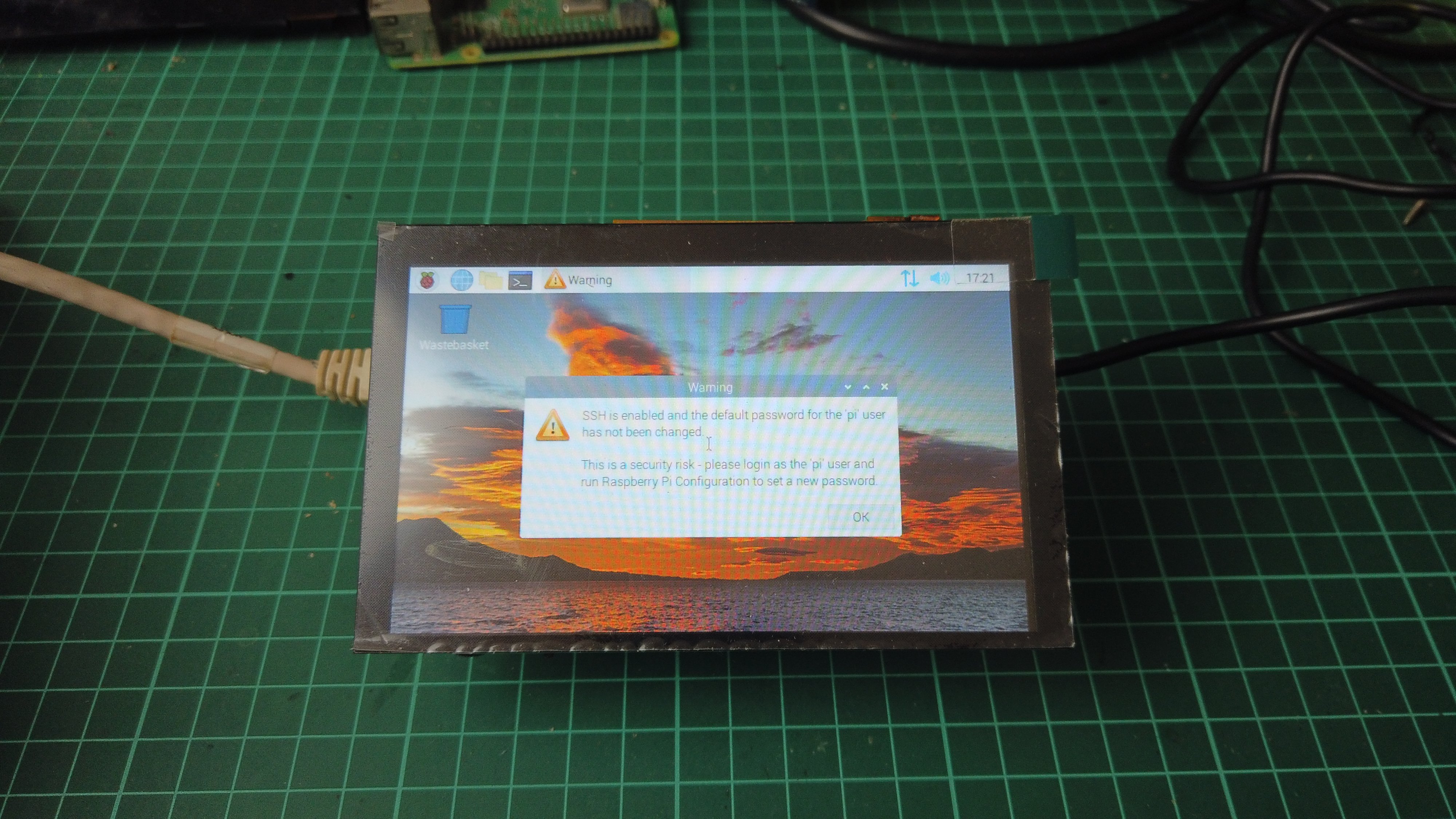
Next we restart the Raspberry Pi, and we can observe the screen displays the Raspberry Pi window.
The next is to enable the USB 2.0 port. By default the USB port on the CM4 is disabled to save power. To enable it, add the following to the config.txt file:
dtoverlay=dwc2,dr_mode=host
That' all for now, in the next tutorial we shall see how to interface this device to other electronic components.
Resources
Thank You
Thanks for reading this tutorial. If you have any technical inquiries, please post at Cytron Technical Forum.
"Please be reminded, this tutorial is prepared for you to try and learn.
You are encouraged to improve the code for a better application."