 International
 Singapore
 Malaysia
 Thailand
 Vietnam
Your shopping cart is empty!

BLTouch Installation for Ender 3 with 32-bit V4.2.2 Board
BLTouch is a popular tool to perform Auto Bed Leveling for 3D Printer. This tutorial shows the detailed steps to install BLTouch V3.1 onto Ender 3 32-bit V4.2.2 board. Most of the steps are applicable to V4.2.7 board, except the firmware version.
Hardware
This tutorial will be based on:
- Ender-3 3D Printer with 32-bit board, I get V4.2.2 board
- BLTouch V3.1 Kit for Ender 3/PRO 8-bit and 32-bit board
The Choices.....
As there are many ways to install the BLTouch due to different cablings, different board versions, and different firmware versions, allow me to list out the general steps here:
- Install the BLTouch to Hotend
- Install the wiring to the main board, ACCORDINGLY and PROPERLY
- Tidy up the wiring
- Download the correct firmware according to 3D printer model, board version and wiring
- Format a microSD to FAT32, put the firmware.bin file into the microSD card, change the filename to unique filename.
- Update the firmware into the 32-bit controller board
- Check if the BLTouch is working
- Level the bed
- Set Z-offset
- Store the Mesh Level and Z-offset
- Configure Sciler to load mesh bed leveling before every print, or perform bed leveling before every print.
- Enjoy the ABL (Auto Bed Leveling)!
Swap the Wiring
This BLTouch Kit is meant for 8-bit and 32-bit board, however, the default wiring is for 8-bit (green) board with an adapter (hack the buzzer pin for LCD). No swapping of wires is necessary for 8-bit board.
For 32-bit board, we will need to do a minor adjustment to the wiring. This is a MUST step, as the swapped wires are VCC (+ve 5VDC) and GND (0V). If you do not swap the wires, you will damage the BLTouch and it is not under warranty.
For 32-bit Board V4.2.2 or V4.2.7 ONLY
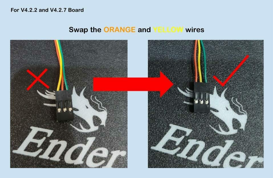
If you get this kind of wiring, please make sure to swap the wiring, or else you will BURN the BLtouch and maybe the controller board too.
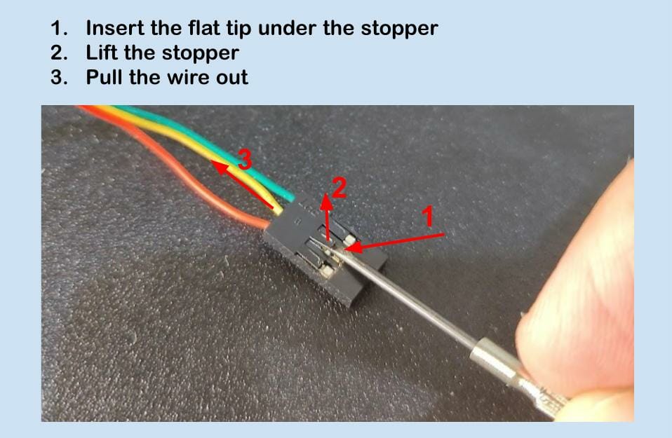
It is quite simple to pull out the wire from the connector. Just use a flat or pointy pin-like flat screwdriver to lift up the stopper (black) that holds the metal pin, then pull the wire out.
Install the BLTouch to Hotend Assembly
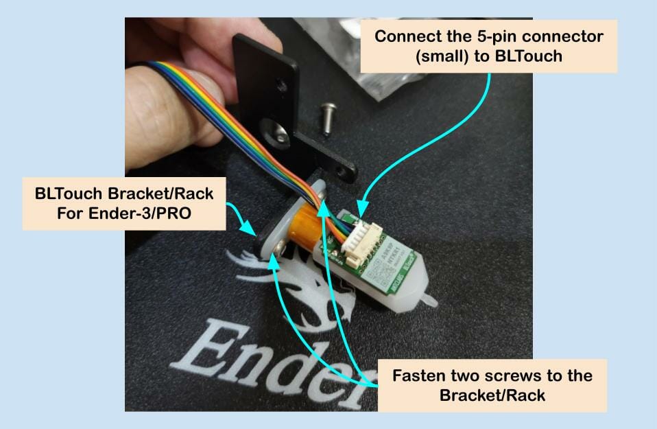
After the minor modification on the wire, now we need to install the BLTouch to the Hotend assembly.
- Connect the cable to BLTouch, the 5-pin small connector.
- Mount the BLTouch to the Bracket/Rack, please mind the orientation. The cable/connector should face the Hotend assembly.
- Fasten the two screws to secure the BLTouch to the Rack.
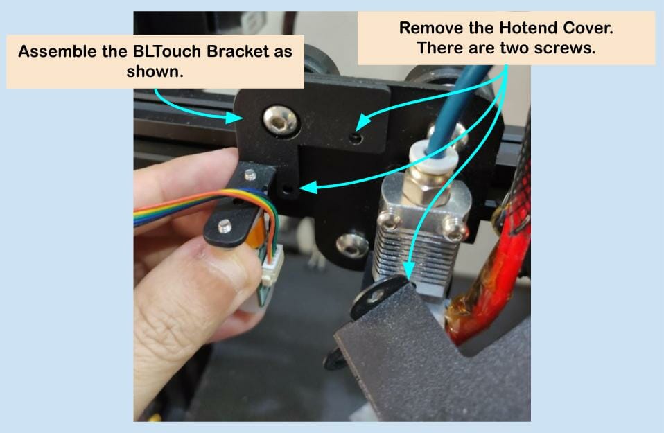
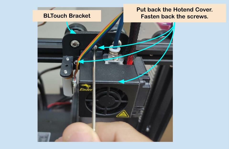
Now, remove the screws (2) that secure the hotend cover. And mount the BLTouch together with the bracket/rack.
Put back the Hotend cover and fasten back the two screws. Do mind the BLTouch wires, they should be near the hotend.
Tidy up the BLTouch cable together with the hotend wiring. No cable tie is needed for now. If you want to put it inside the cable management sleeve, please do it now.
The cable should be routed into the controller box as other wires. Open the cover of the controller box. For Ender 3, the cover is at the top, Ender 3 PRO is at the bottom of the 3D printer.
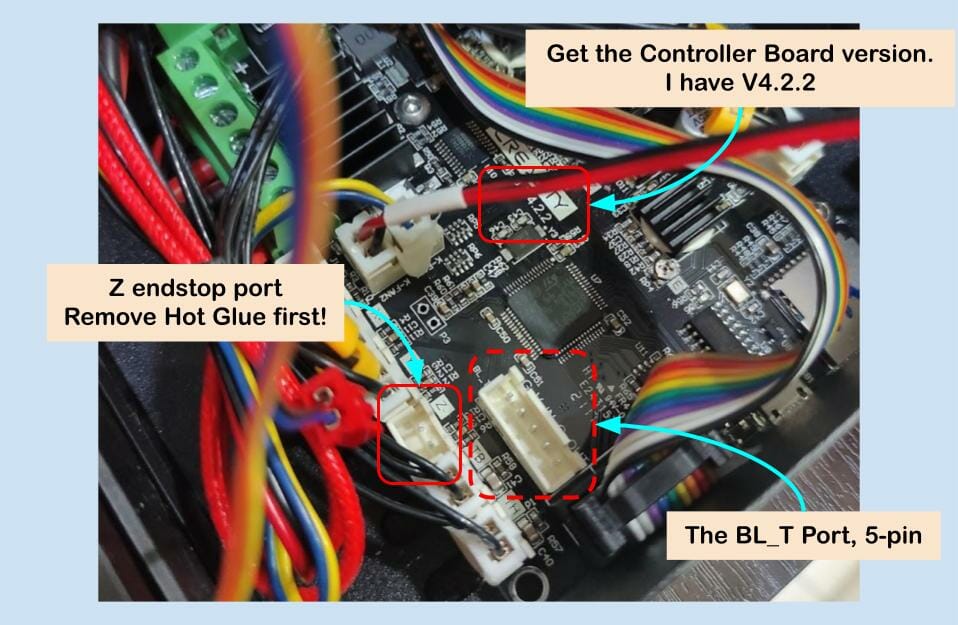
You will need to connect the BLTouch cable to a certain port and also remove the original Z end-stop connector from the board. You will also need to check the controller board version.
- Board version, I have V4.2.2 with me.
- Remove the Z endstop connector from the port. Please mind the hot glue from the manufacturer. Do not pull the cable with force, remove the hot glue first, then only pull the cable off the port.
- Connect the cable (two different connectors) to the BL_T port, 5-pin socket.
After removing the Z endstop cable from the port, let’s complete the wiring for BLTouch.
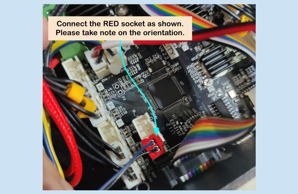
Connect the Red connector from the BLTouch to two side pins of the BL_T port (5-pin), near to LCD ribbon cable port.
Next, connect the 3-pin connector that you swapped the Orange and Yellow earlier. Again, check the orientation. The WRONG connection will damage the BLTouch and even the controller board.
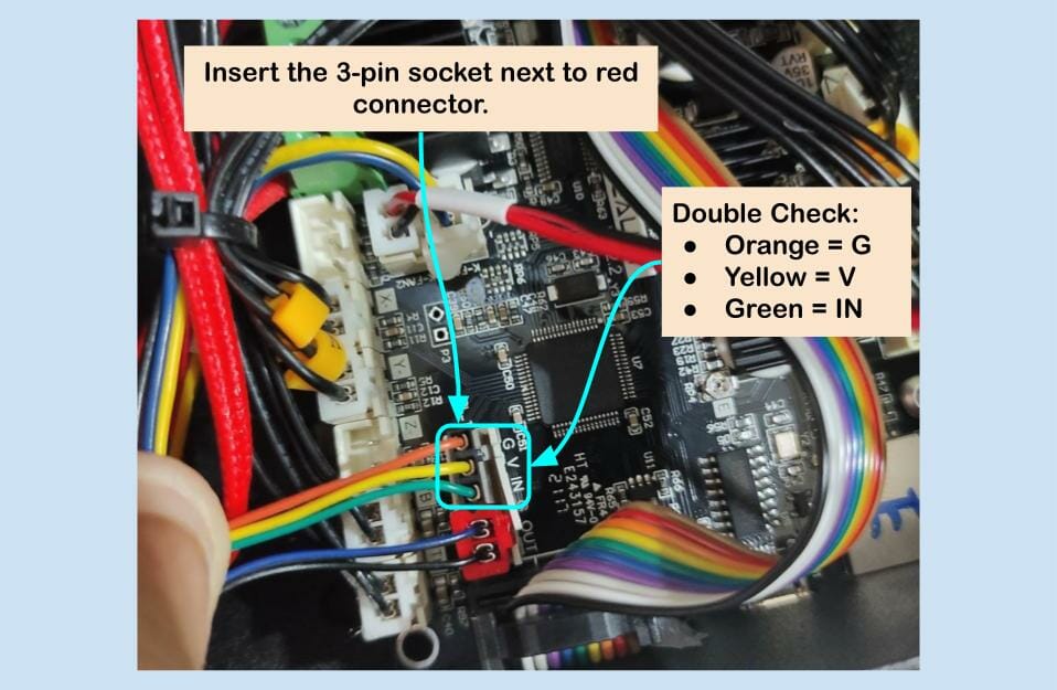
The color and function:
- Orange = Ground (0V)
- Yellow = VCC (5VDC)
- Green = PWM Signal to control the servo on BLTouch
Make sure the connectors are inserted properly, especially the red connector. You can close the cover, but do not fasten the screws yet. You might need to recheck the connection.
The Firmware Update
BLTouch without a correct firmware update is useless. So please follow the steps carefully. You might need to troubleshoot for hours if the firmware is not correct.
And here is where the board version comes in and which port of the Red connector of BLTouch inserted will decide that too.
1. Get the Correct Firmware
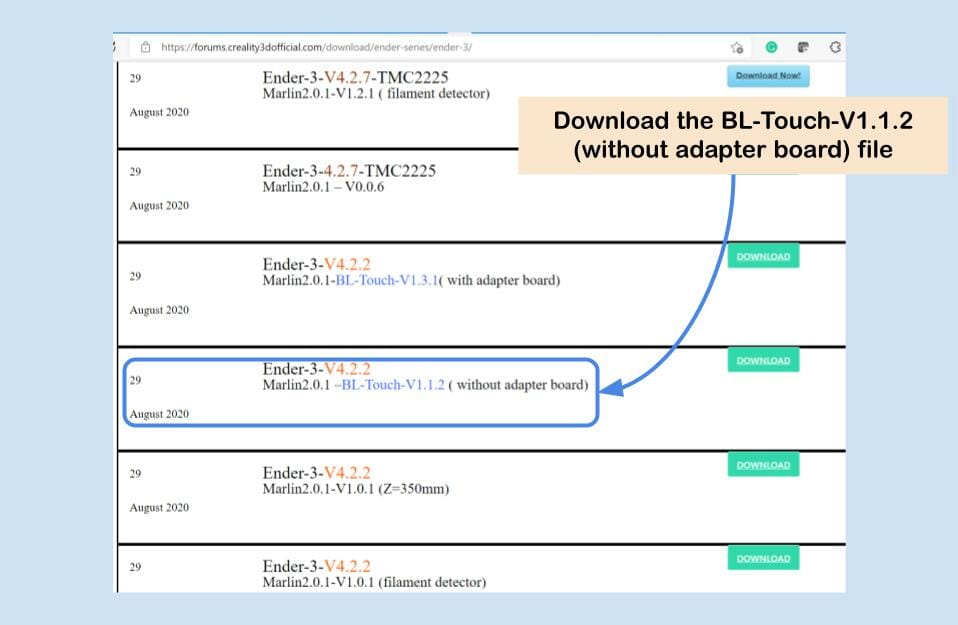
Let’s get started. Go to: https://forums.creality3dofficial.com/download/ender-series/ender-3/. As I have V4.2.2 board, I will need the right firmware for it. So search for “Ender-3-V4.2.2 Marlin2.0.1 –BL-Touch-V1.1.2 ( without adapter board)”, and download the file. If you have Ender-3-V4.2.7 firmware.
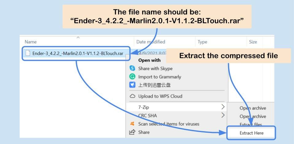
The downloaded file should be a compressed file with an extension of “rar”, with a file name “Ender-3_4.2.2_-Marlin2.0.1-V1.1.2-BLTouch”. Extract the compressed file.
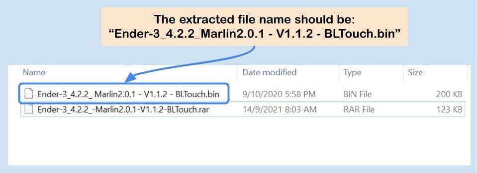
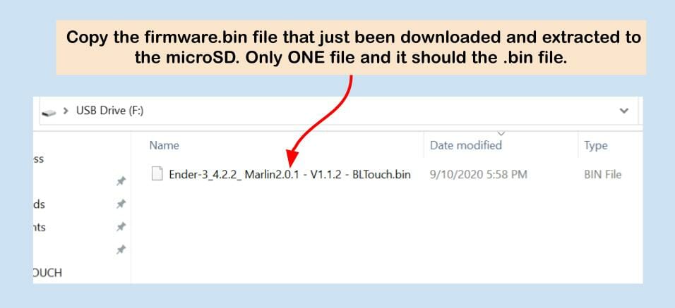
After extraction, there should a file with an extension of “bin”. That is the firmware file that we need. As of the time this tutorial is written, the file name is “Ender-3_4.2.2_ Marlin2.0.1 – V1.1.2 – BLTouch”.
2. Get the microSD Card Ready
Get ready a microSD card to update the firmware to the 32-bit board. If you do not have an additional microSD card to spare, you can still use the microSD card that comes with the 3D printer. But you need to backup the content in the microSD card as we need to format the microSD and the content will be wiped out. And there should be only ONE firmware file in the microSD for updating the controller board. We have tested microSD card with capacity of 8GB, 16GB, 32GB and 64GB for updating the firmware to V4.2.2 board, they work fine. But formatting microSD card larger than 16GB will need special software to format into FAT32, at least on Windows.
Anyway, get a microSD card, with a microSD card USB adapter, and plug it into the computer’s USB port.
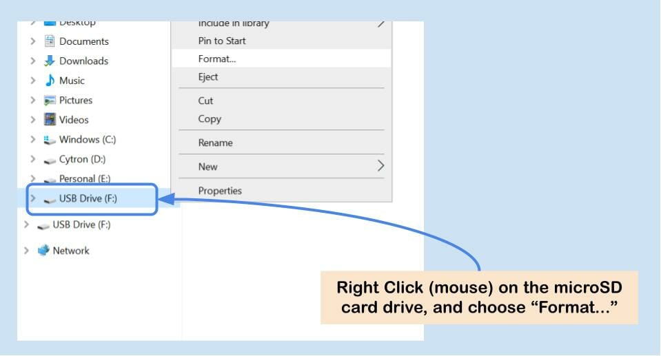
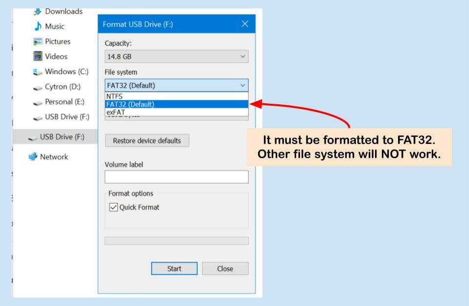
Right-click the drive and format the microSD card into FAT32.
Now the microSD card is ready for the firmware file. Copy the firmware file that you have just extracted into the microSD card. Make sure there is ONLY ONE file and it MUST be “.bin” extension. That is the binary file for the microcontroller on the controller board, sometime we called it machine code.
Updating the 3D Printer with the Firmware
Now, with the hardware installation of BLTouch completed, both the mounting and the wiring. And the correct firmware loaded into the FAT32 formatted microSD card, the last step before the BLTouch can start helping you to perform Auto Bed Leveling is to UPDATE the firmware into the controller board. So let’s do it.
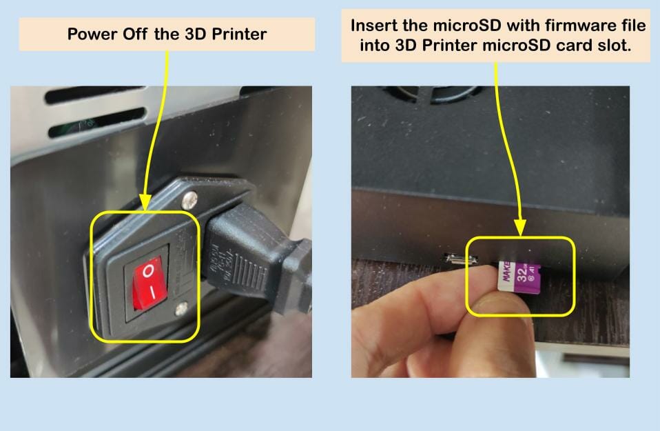
Get the microSD out of the microSD adapter. Power off the 3D Printer and insert the microSD into the microSD card slot of 3D Printer.

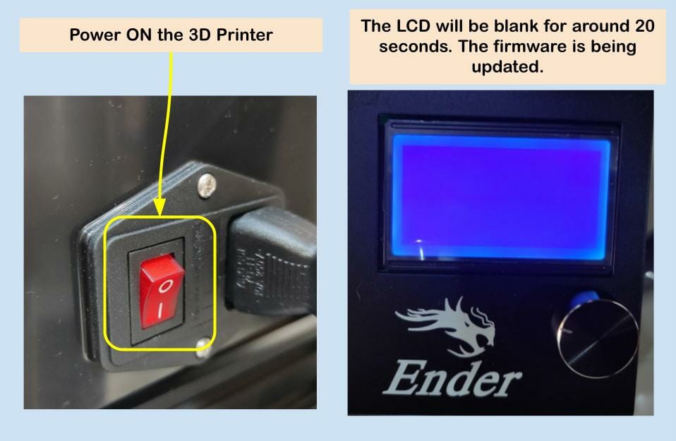
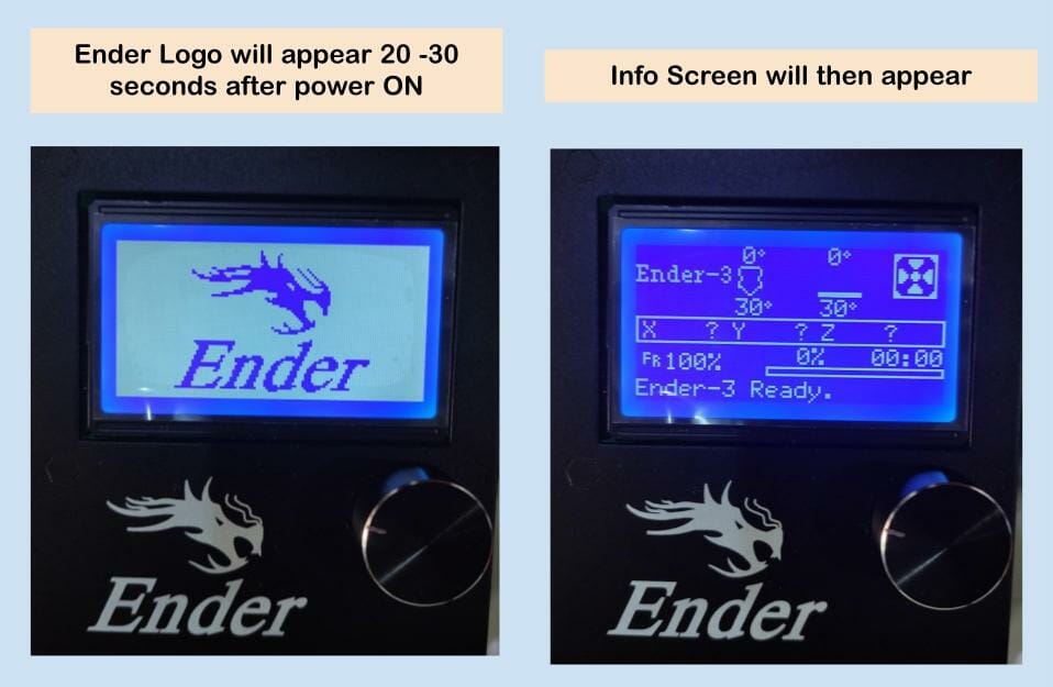
Power ON the 3D Printer after the microSD card is inserted properly with the sound of a click. Observe the LCD, it will remain blank for around 20 to 30 seconds. That is normal as the controller is updating the firmware from the microSD card.
Ender logo will then appears for a short while, followed by the info screen.
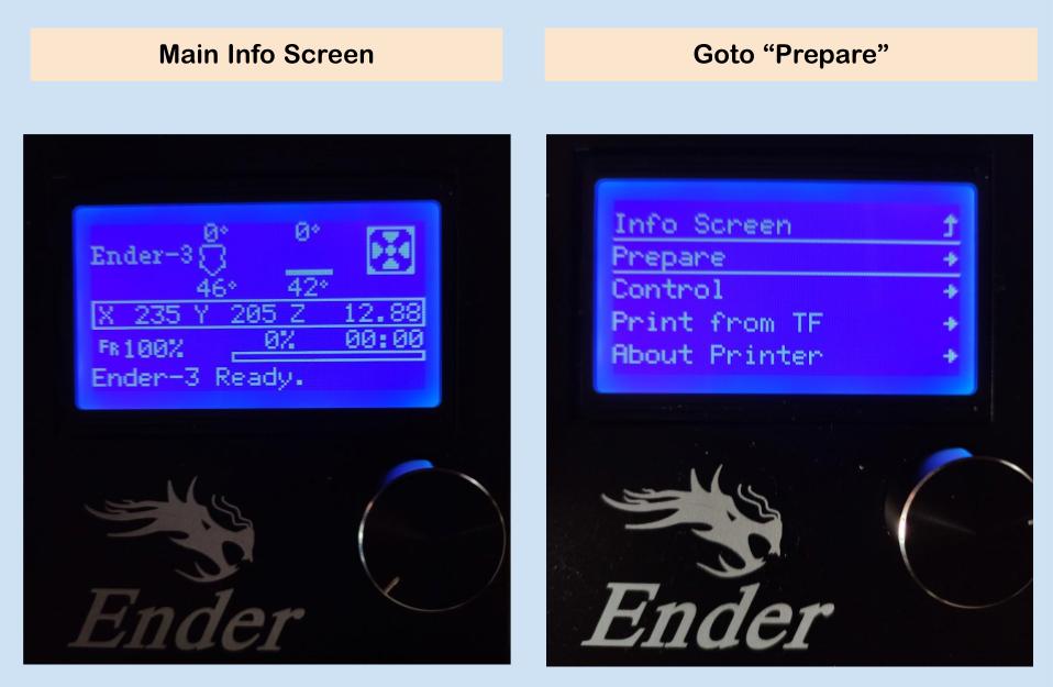
You can further goto Printer Info to display the firmware version and date.
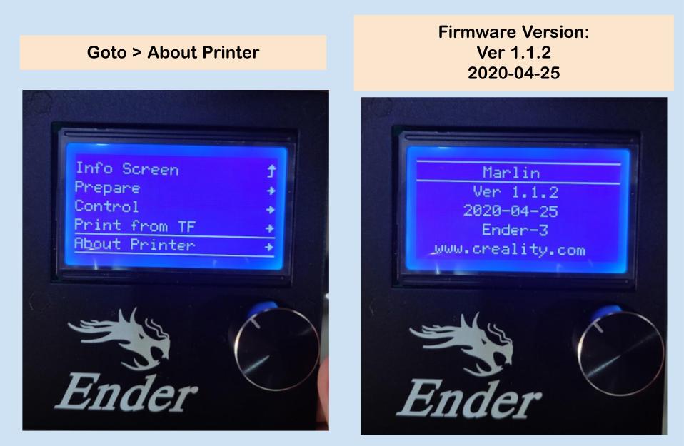
If the firmware loaded correctly, the screen should display:
Marlin
Ver 1.1.2
2020-04-25
Ender-3
Congrats! You have installed the BLTouch on your Ender 3 3D Printer.
Using the BLTouch
Yeah! Of course, we want to utilize the BLTouch for our 3D printer in helping us get the best 1st layer. Yet, there are steps that you need to configure, at least the mesh bed level data and Z offset are needed. You will need to store these settings too.
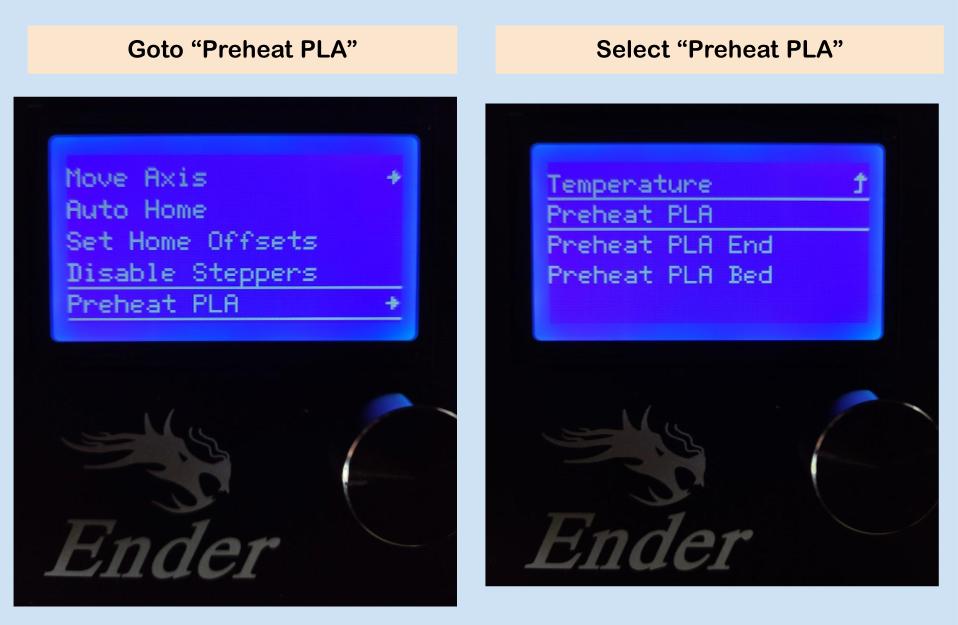
For the default Creality firmware, please follow these steps:
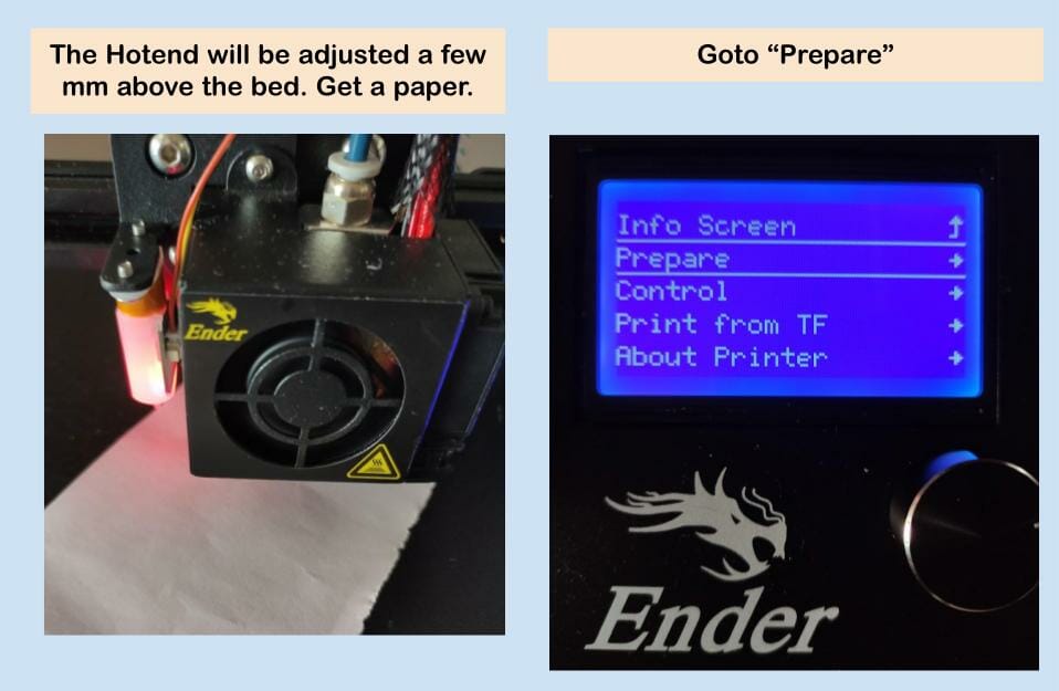
- Get Z offset Value, it should be a negative value. A positive value is not valid. Depending on the distance between the bed (center) and to the nozzle, it should range from -2.0mm to -4.0mm.
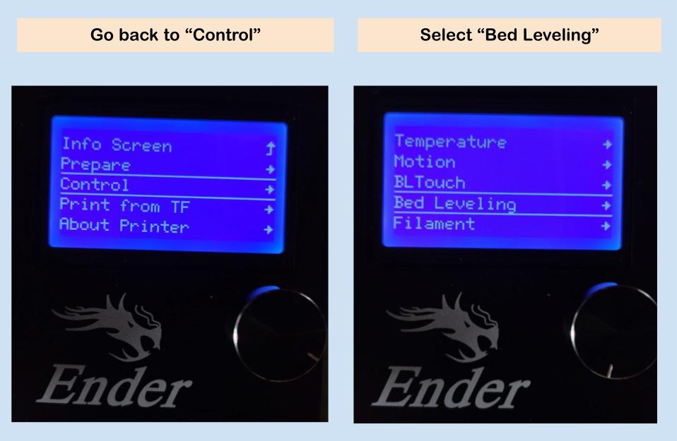
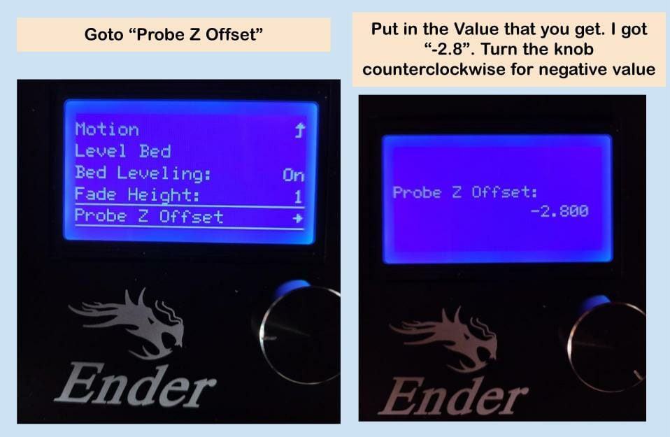
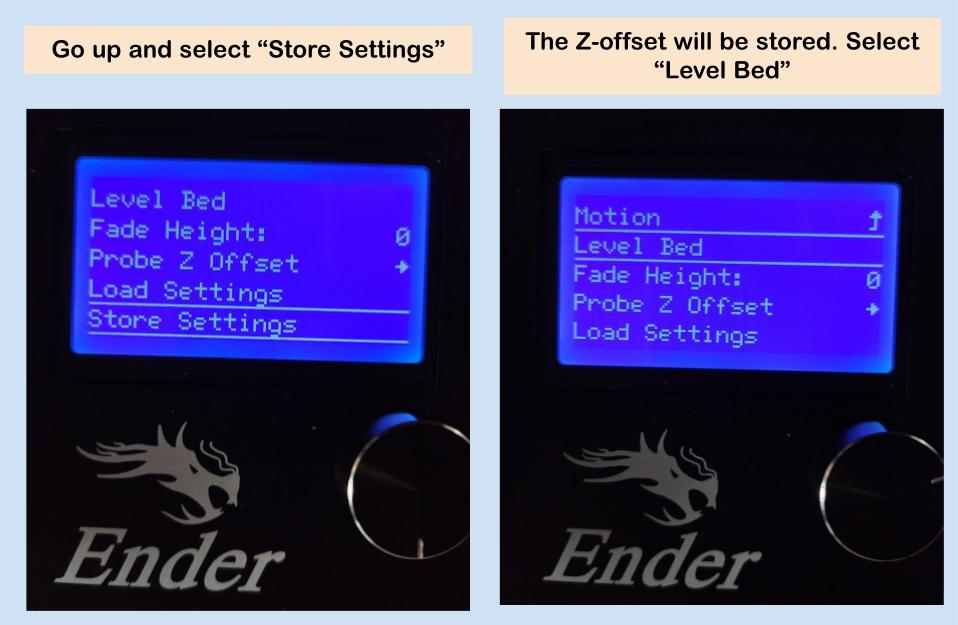
- Set the Z offset value under “Probe Z Offset” and then “Store the Settings”.
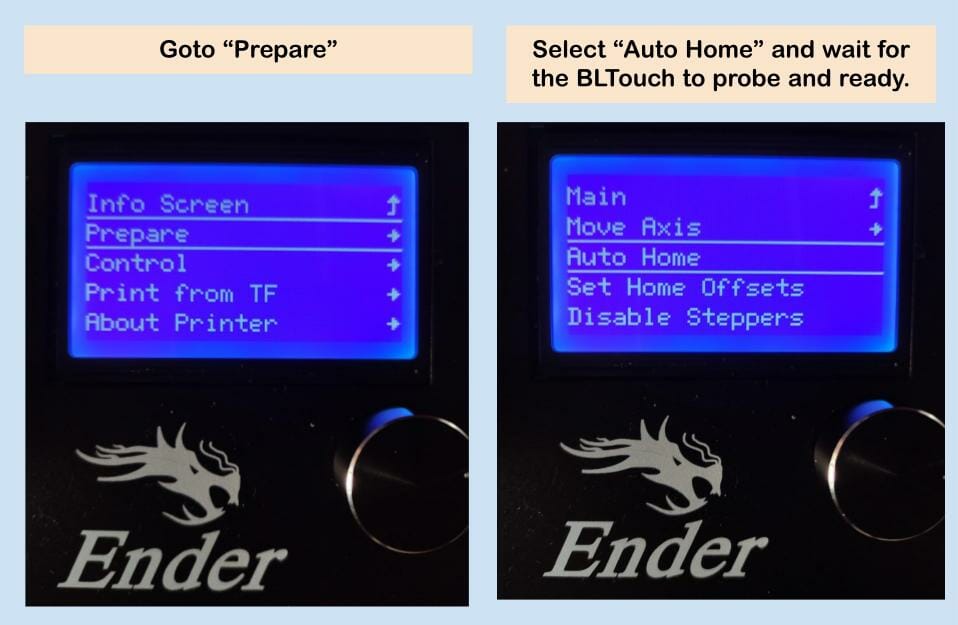
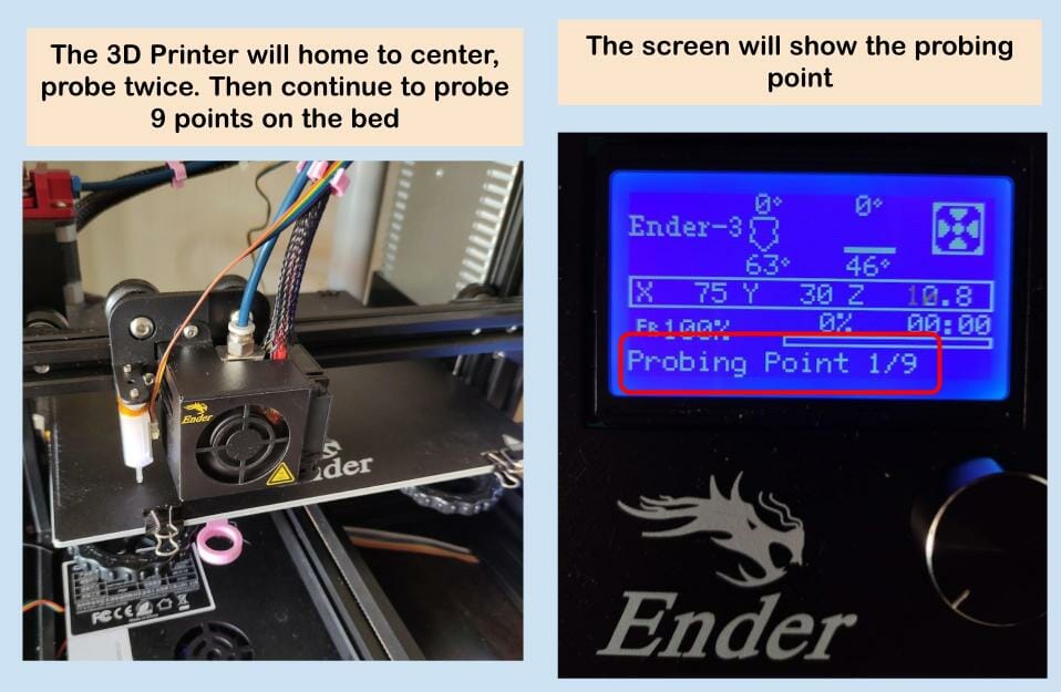
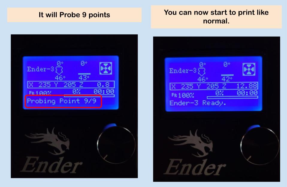
- Perform Bed Leveling to probe 9 points on the bed.
- Start printing like normal.
- You might also need to make some modifications to your slicer too, depending on your preferences.
Again, this is based on Creality firmware V1.1.2 for Ender-3. This section is to get the Z offset, store it in the printer, then level the bed.
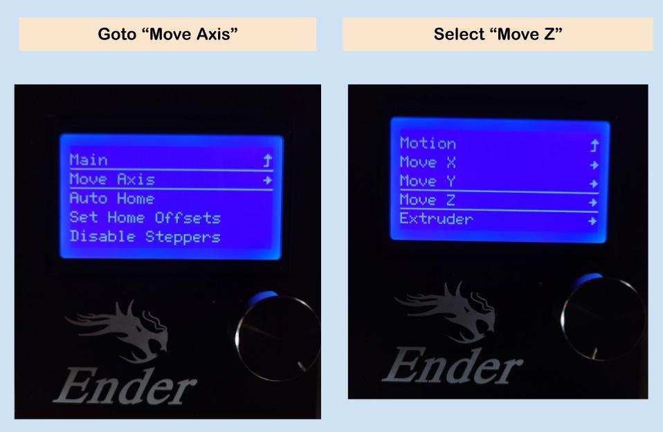
Get Z Offset, Store it and Bed Leveling with BLTouch
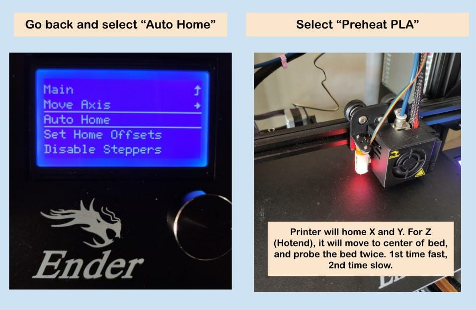
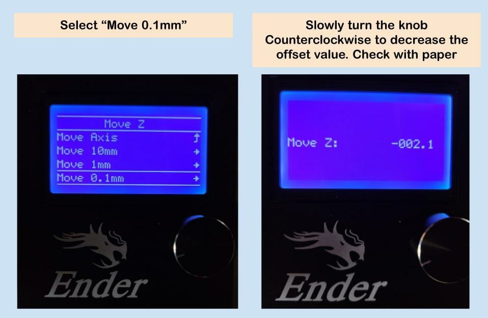
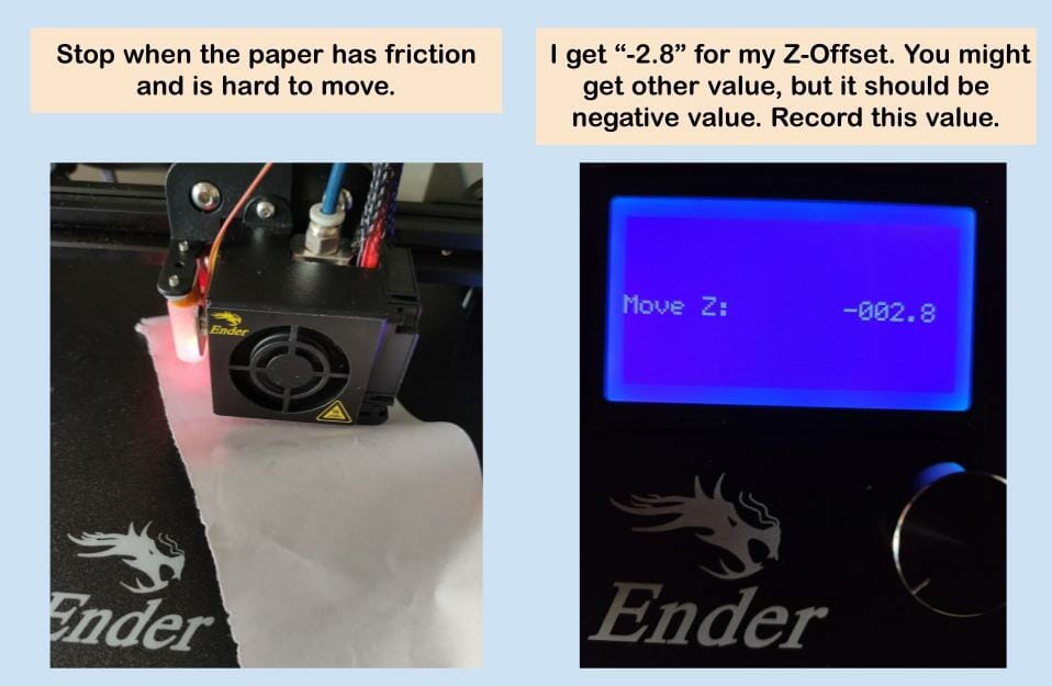
For this Probe Z Offset, the hotend should be floating in the air, so please do not adjust the nozzle to touch the bed. Just key-in the value you get just now.
Slicer Settings
Again, there are several choices. You can still print the normal gcode that you generated earlier. But you might need to perform the ABL from the printer menu manually before every print. Or you can modify the “Start G-code” on the slicer. I am using Cura 4.10.0.
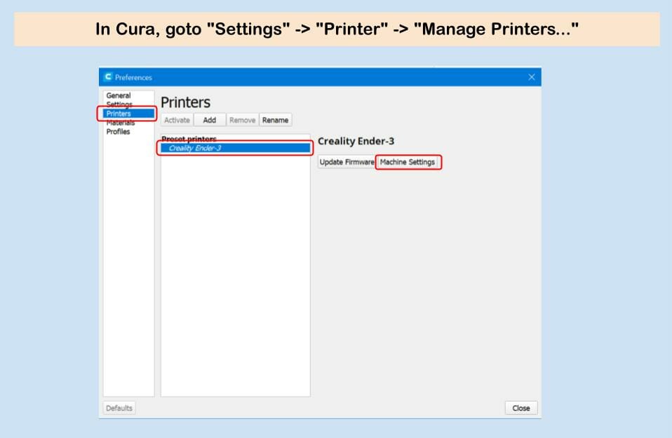
In Cura, goto “Settings” -> “Printer” -> “Manage Printers…”. Select the “Printers”, and the Printer you want to modify the gcode, then “Machine Settings”
A G29 (ABL) must be placed on the line after G28 (homing) in the start gcode section of your slicer. G28 cancels any probed meshes so it must be in this order.
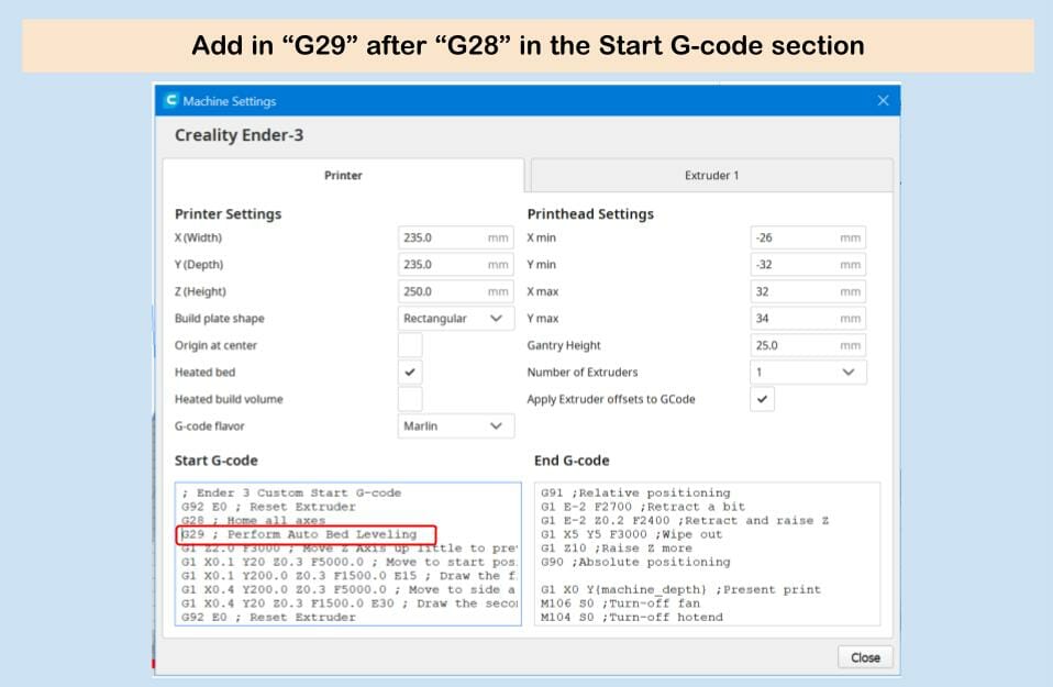
Close the “Machine Settings” window and go back to Cura. Slice your STL file as you did. The new gcode generated will perform ABL before every print.
To understand more about Slicer settings, please visit Micheal from Teaching Tech. He has a comprehensive tutorial about BLTouch here.
Tiny Up
If everything is working fine, please do tidy up the cabling with the cable ties provided in the BLtouch kit. Make sure it does not accidentally tangle with the bed or extruder.
Summary
It took me less than 30 minutes to upgrade my Ender-3 with this BLTouch, and I like it. But that is because I know the tips and tricks. To use Creality default BLTouch firmware (V1.1.2), the BLTouch sensor detection connector (Red connector) CANNOT be connected to the original Z endstop port on the 32-bit controller board. Instead, it should be connected to the 5-pin port that labeled “BL_T”.