 International
 Singapore
 Malaysia
 Thailand
 Vietnam
Your shopping cart is empty!

Sound Level Detector using Maker UNO paired with ESP8266 Grove WiFi on Blynk
- Hao Zhen Goh
- 18 Oct 2021
- Tutorial
- Beginner
- 606
Having a noisy surrounding at home? Make yourself a sound level detector and notify the noise maker through Blynk App using Maker UNO paired with an ESP8266 Grove WiFi.
Hardware and Software Preparation
Hardware:
- Maker UNO (Arduino UNO compatible) x1
- Grove WiFi 8266 x1
- Base Shield V2 x1
- Grove Sound Sensor x1
Software:
- Arduino IDE
- Blynk
Before You Start
Hardware Setup
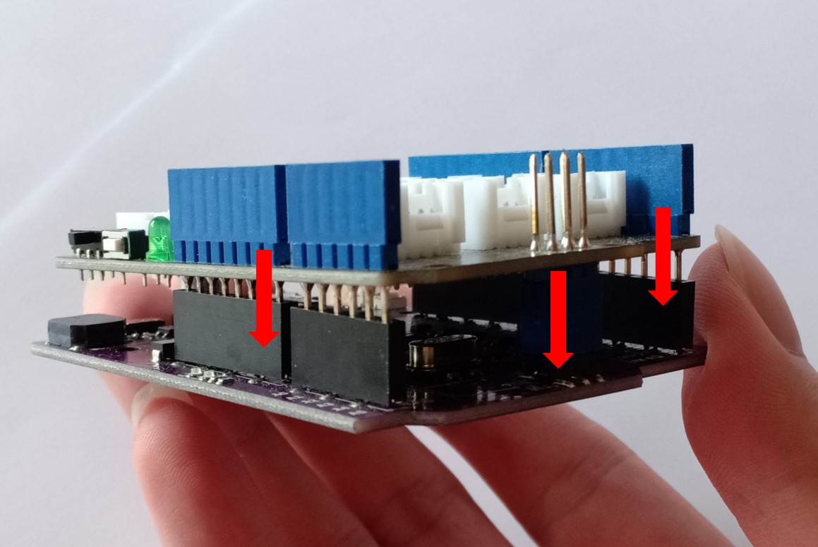
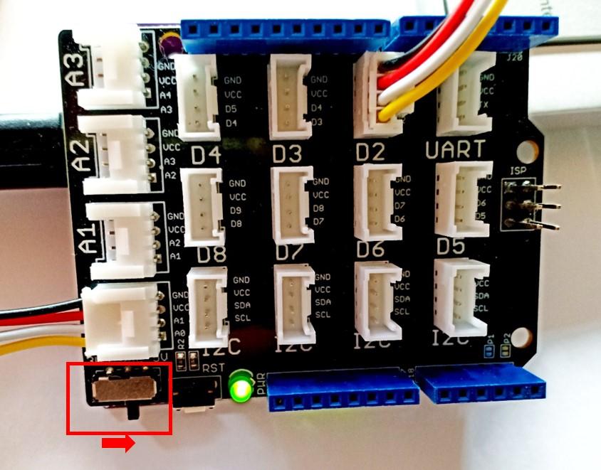
1. Connect the Base Shield to the Maker UNO board.
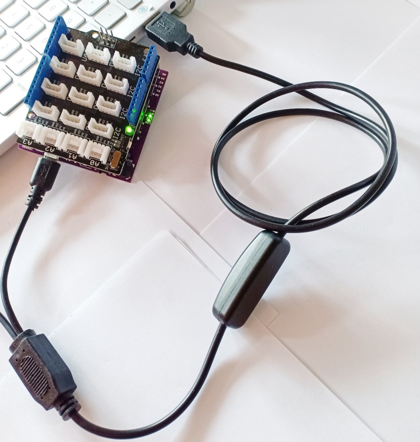
2. Connect the USB cable to your computer and Maker UNO board.
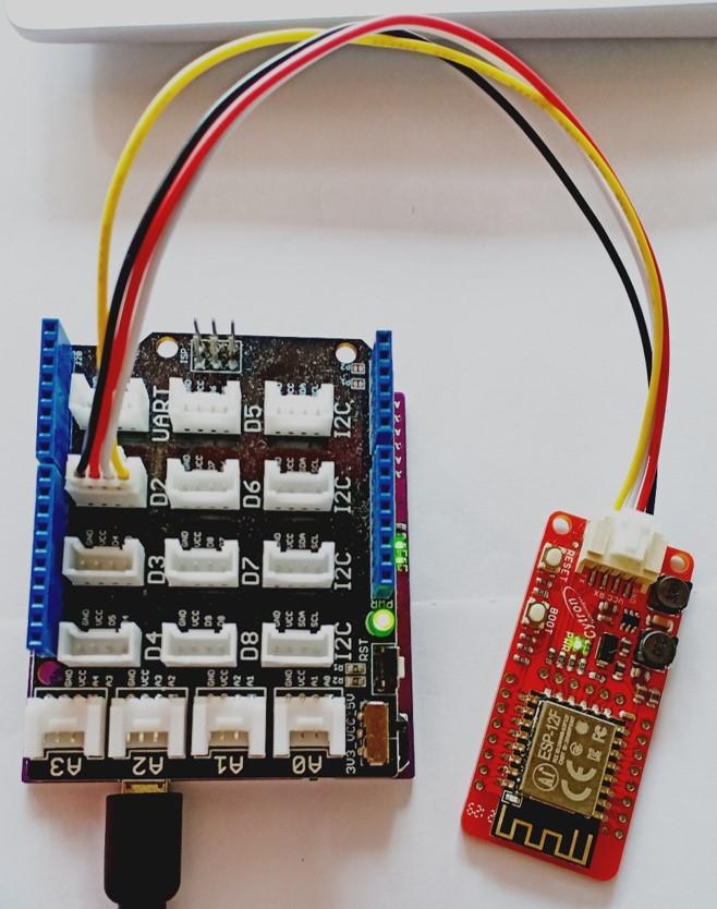
3. Connect the Grove 8266 WiFi to D2 port on your Base Shield.
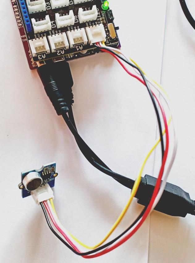
4. Connect the Grove Sound Sensor to A0 port on your Base Shield.
5. Set the input voltage of your Base Shield which is connected to your Maker UNO to 5V.
Software Setup
On Arduino
1. Download and install Arduino IDE on your computer if you don’t have one.

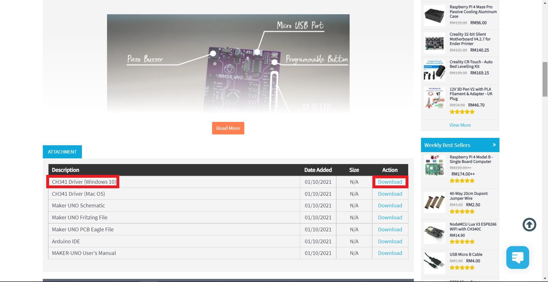
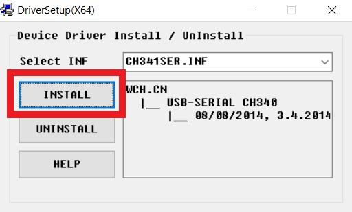
2. Download CH341 here if you are using Maker UNO for the first time. Open the downloaded file and install CH341 Driver which is used for Maker UNO.
Note: You may check the Port number for your Maker UNO in your computer’s “Device Manager”.

3. Select the correct port in Tools >> Port: >> COM X for your Maker UNO board.

4. Select Sketch >> Include Library >> Manage Libraries. Then search for “Blynk” and click the library named “Blynk” and install.

5. Go to this link containing an additional library for Blynk, select “Code” and “Download ZIP”.

6. Go to your Arduino IDE and select Sketch >> Include Library >> Add .ZIP library… and select the ZIP file that you have downloaded.

On Blynk
1. Install Blynk IoT app on your smartphone and create a new Blynk account if you don’t have one.
Follow the guide here on how to install the Blynk app, create a new Blynk account and get the Auth Token of your project.
What Does the Code Do?
- Able to connect to WiFi.
- Able to connect to your Blynk project.
- Able to detect the sound level of surroundings.
- Able to notify and show the sound level in your Blynk project when the sound level exceeds the threshold value.
Let’s Start Coding
Step 1: Blynk Widget Setup
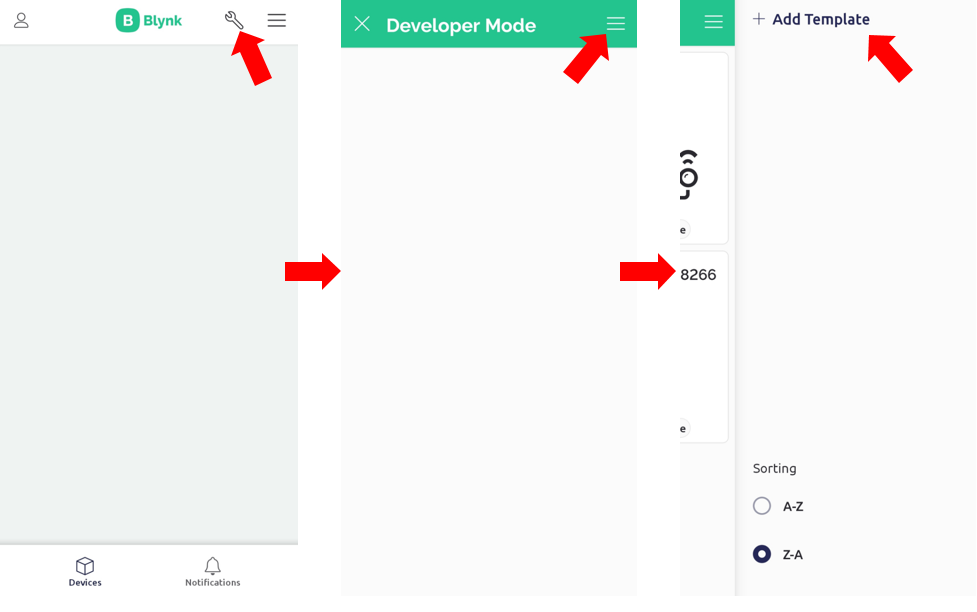
1. Create a new template and give it a special name (for example: Grove WiFi 8266).
You may refer to the Step 1 mentioned in that guide.
We will show you the steps on the Mobile App version to set up the datastream virtual pins and widgets. The web browser version will be very similar to what is being shown here.
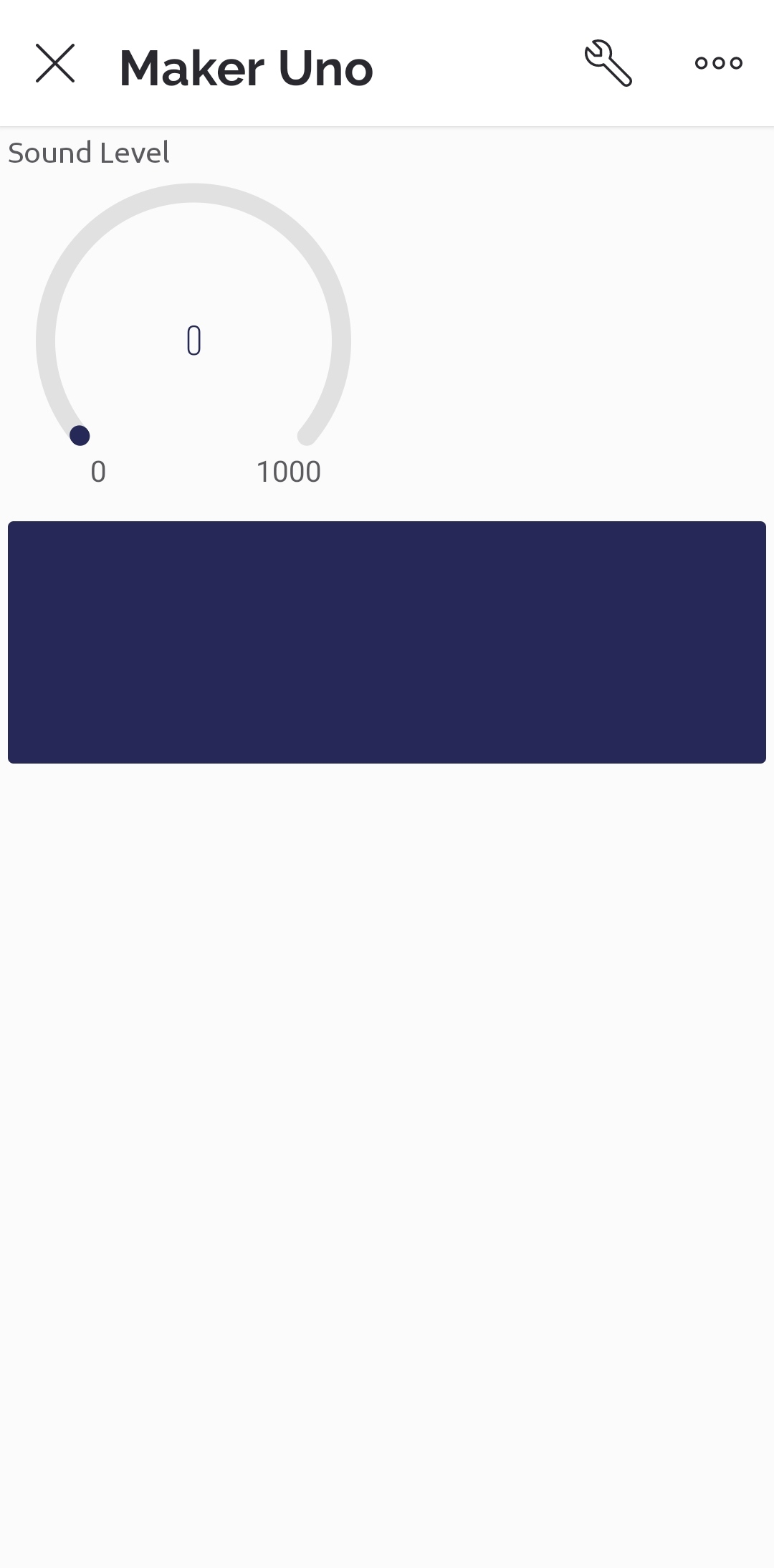
2. Within the new template, create a new datastream for the following virtual pins.
- V1 : Sound level, integer
- V2: LED, integer
- V3: LCD, string
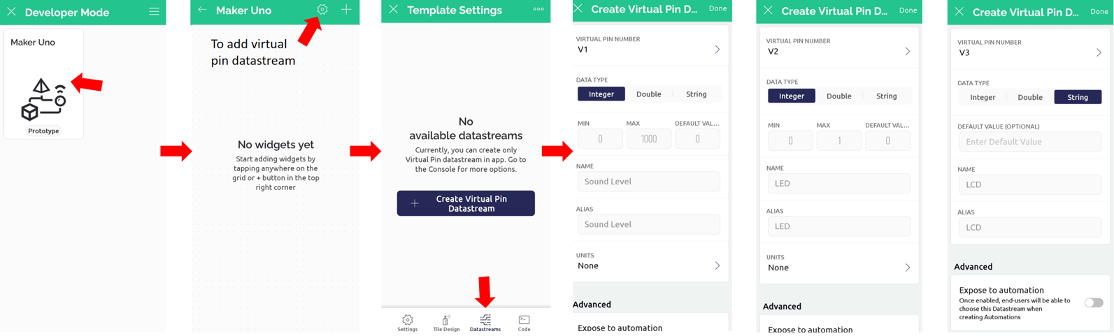
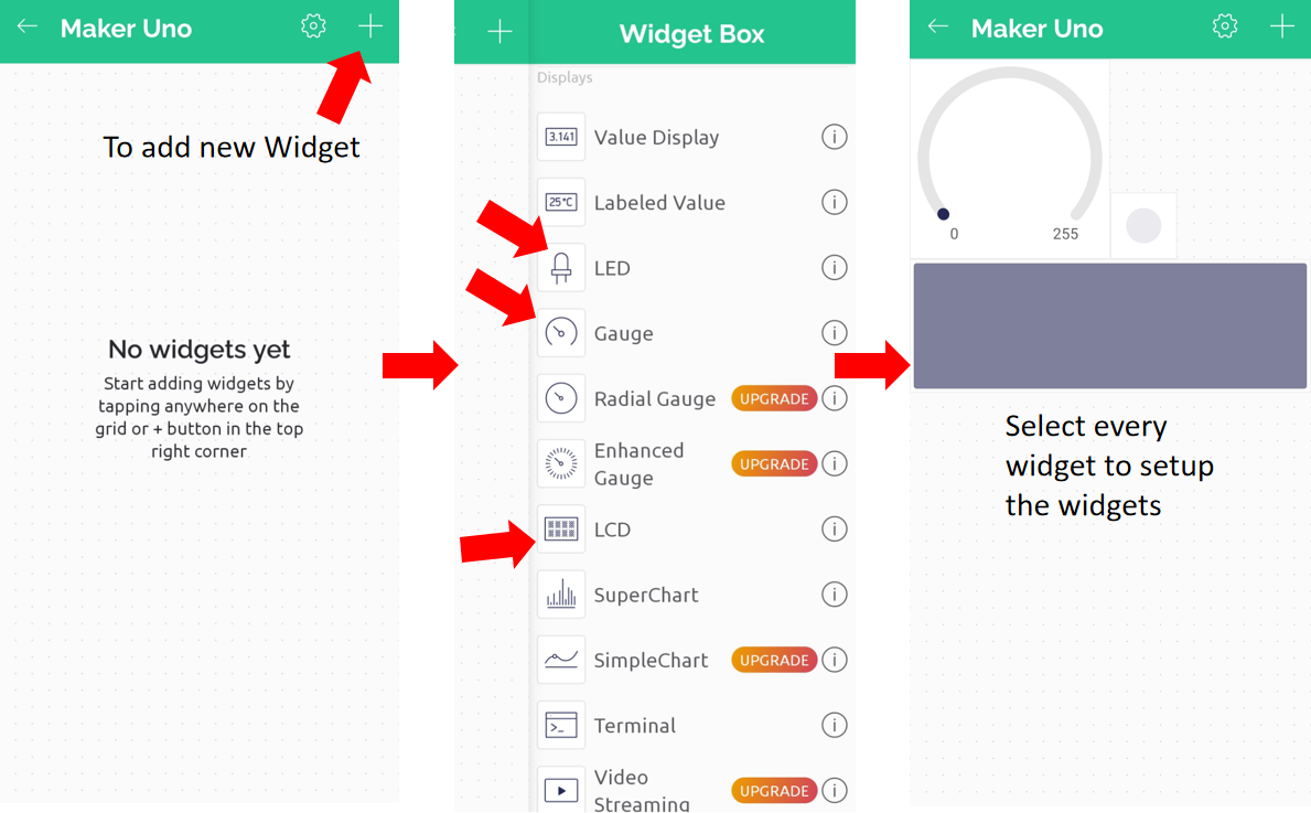
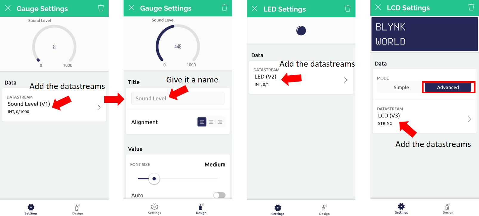
3. Add new widgets into your template and set up the new widget by selecting the correct datastream virtual pin that you have created. Select each of them and set up all the widgets.
- Gauge
- LED
- LCD
4. On the Blynk IoT app, add new device to create a new Blynk IoT project.
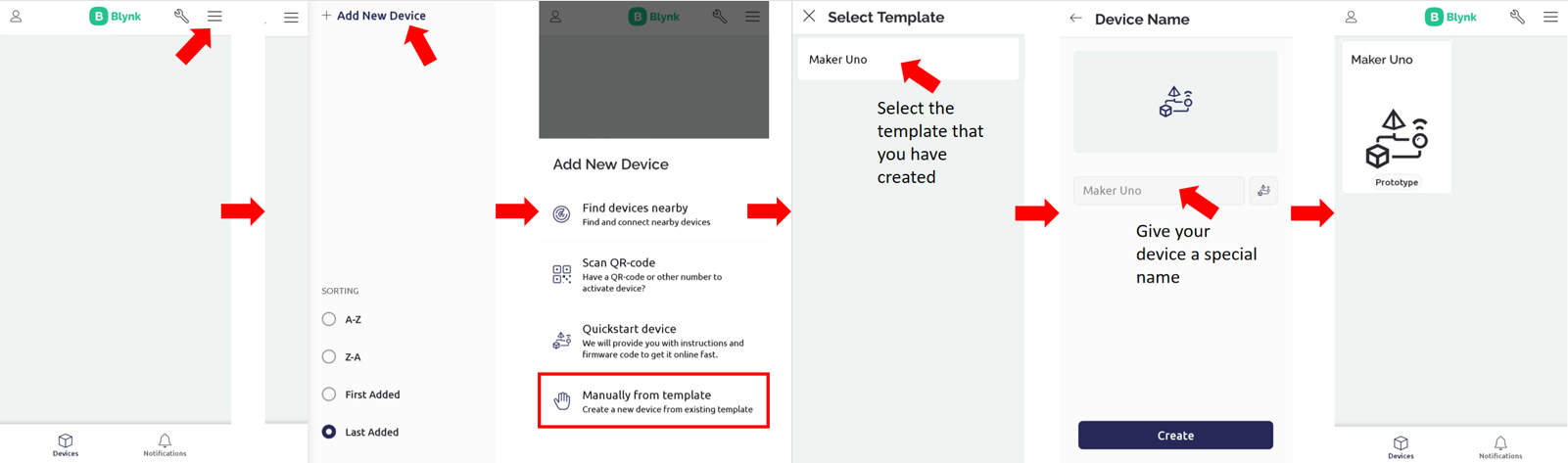
5. In the end you will get something like this:
Step 2: Change the baudrate of Grove WiFi 8266
The baudrate of the Grove 8266 WiFi module is set at 115200 by default. But since we will be using the software serial library on the Maker UNO, it’s more reliable to communicate at a lower speed. Hence, you have to change the baudrate of Grove WiFi 8266 to 9600bps first before using it in this project.
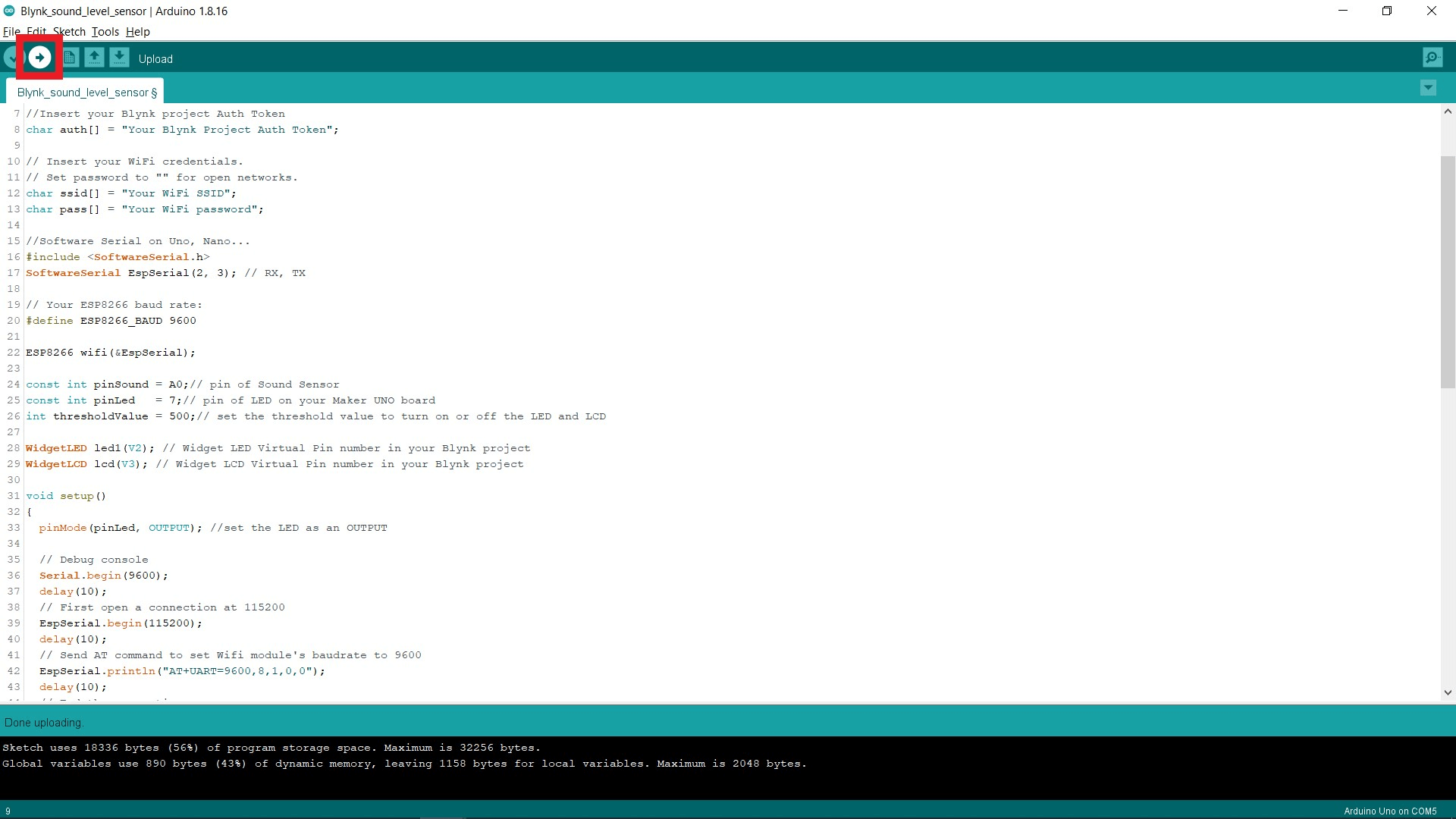
1. Copy and paste the following code into your Arduino IDE.
#include

// or Software Serial on Uno, Nano...

#include

SoftwareSerial EspSerial(2, 3); // RX, TX
// Your ESP8266 baud rate:

#define ESP8266_BAUD 9600
ESP8266 wifi(&EspSerial);
void setup()

{

  // Debug console

  Serial.begin(9600);

  delay(10);

  // First open a connection at 115200

  EspSerial.begin(115200);

  delay(10);

  // Send AT command to set Wifi module's baudrate to 9600

  EspSerial.println("AT+UART=9600,8,1,0,0");

  delay(10);

  // End the connection

  EspSerial.end();

  // Reopen the connection at 9600

  EspSerial.begin(9600);

  EspSerial.println("AT");

}
void loop()

{

}
2. Upload the code to your Maker UNO Board and wait for it to complete the uploading process.
Note: Make sure you have selected the correct port in Tools >> Port: >> COM X.

If you wish to change it back to 115200 baudrate, copy the following code to your Arduino IDE and upload it to your Maker UNO while the Grove 8266 WiFi module is connected to the D2 port.
#include

// or Software Serial on Uno, Nano...

#include

SoftwareSerial EspSerial(2, 3); // RX, TX
// Your ESP8266 baud rate:

#define ESP8266_BAUD 9600
ESP8266 wifi(&EspSerial);
void setup()

{

  // Debug console

  Serial.begin(9600);

  delay(10);

  // First open a connection at 9600

  EspSerial.begin(9600);

  delay(10);

  // Send AT command to set Wifi module's baudrate to 115200

  EspSerial.println("AT+UART=115200,8,1,0,0");

  delay(10);

  // End the connection

  EspSerial.end();

  // Reopen the connection at 115200

  EspSerial.begin(115200);

  EspSerial.println("AT");

}
void loop()

{

}
Step 3: Upload the Code
1. Copy and paste the following code into your Arduino IDE.
#define BLYNK_PRINT Serial
#define BLYNK_TEMPLATE_ID "Your Template ID"

#define BLYNK_DEVICE_NAME "Maker Uno"
#include

#include
//Insert your Blynk project Auth Token

char auth[] = "Your Blynk Auth Token";
// Insert your WiFi credentials.

// Set password to "" for open networks.

char ssid[] = "Your WiFi SSID";

char pass[] = "Your WiFi Password";
//Software Serial on Uno, Nano...

#include

SoftwareSerial EspSerial(2, 3); // RX, TX
// Your ESP8266 baud rate:

#define ESP8266_BAUD 9600
ESP8266 wifi(&EspSerial);
const int pinSound = A0;// pin of Sound Sensor

const int pinLed   = 7;// pin of LED on your Maker UNO board

int thresholdValue = 500;// set the threshold value to turn on or off the LED and LCD
WidgetLED led1(V2); // Widget LED Virtual Pin number in your Blynk project

WidgetLCD lcd(V3); // Widget LCD Virtual Pin number in your Blynk project
BlynkTimer timer;
// This function sends Arduino's up time every second to Virtual Pin (5).

// In the app, Widget's reading frequency should be set to PUSH. This means

// that you define how often to send data to Blynk App.

void myTimerEvent()

{

  // You can send any value at any time.

  // Please don't send more that 10 values per second.

  Blynk.virtualWrite(V5, millis() / 1000);

}
void setup()

{

  pinMode(pinLed, OUTPUT); //set the LED as an OUTPUT


  // Debug console

  Serial.begin(9600);

  delay(10);

  // Open the connection at 9600

  EspSerial.begin(9600);

  EspSerial.println("AT");
  Blynk.begin(auth, wifi, ssid, pass);

}
void loop()

{

    Blynk.run();


    int sensorValue = analogRead(pinSound);

    if (sensorValue > thresholdValue) //If the sound level detected is higher than the threshold value...

    {

      //Serial monitor shows the alert message and the sensor value

      Serial.println("Sound Level Too High!");

      Serial.println(sensorValue);

      //LED on Maker UNO will light up

      digitalWrite(pinLed, HIGH);

      //Level H Widget in Blynk shows the sound level

      Blynk.virtualWrite(V1, sensorValue);

      //Widget LED in Blynk will turn on

      led1.on();

      //LCD Widget shows alert messages on the coordinates of x=0, y=0

      lcd.print(0, 0, "Too Loud!");

      //LCD Widget shows alert messages on the coordinates of x=0, y=0

      lcd.print(0, 1, "Keep Quiet!");

      // use: (position X: 0-15, position Y: 0-1, "Message you want to print")

      delay(5000);

      //Clear the LCD Widget in Blynk

      lcd.clear();

      //Turn off LED Widget in Blynk

      led1.off();

      //Reset the Level H Widget in Blynk to 0

      Blynk.virtualWrite(V1,0);

      //Turn off LED on Maker UNO

      digitalWrite(pinLed, LOW);

    }

   else

    {

      //Nothing is turned on

      digitalWrite(pinLed, LOW);

      led1.off();

      lcd.clear();

    }

}
2. Change the Blynk Template ID (Line 3), Blynk Template Name (Line 4), Auth Token (Line 8), WiFi SSID (Line 12) and WiFi password (Line 13) in the code.
Tips: Go File >> Preferences, tick “Display line numbers” to show the line number of your code.
3. Upload the code to your Maker UNO Board and wait for it to complete the uploading process.
Note: Make sure you have selected the correct port in Tools >> Port: >> COM X.
4. Open the Serial Monitor and wait for the WiFi connection, it may take a few seconds until it shows the WiFi connection is successful or not.
Note: Remember to change the Serial Monitor baudrate to 9600.
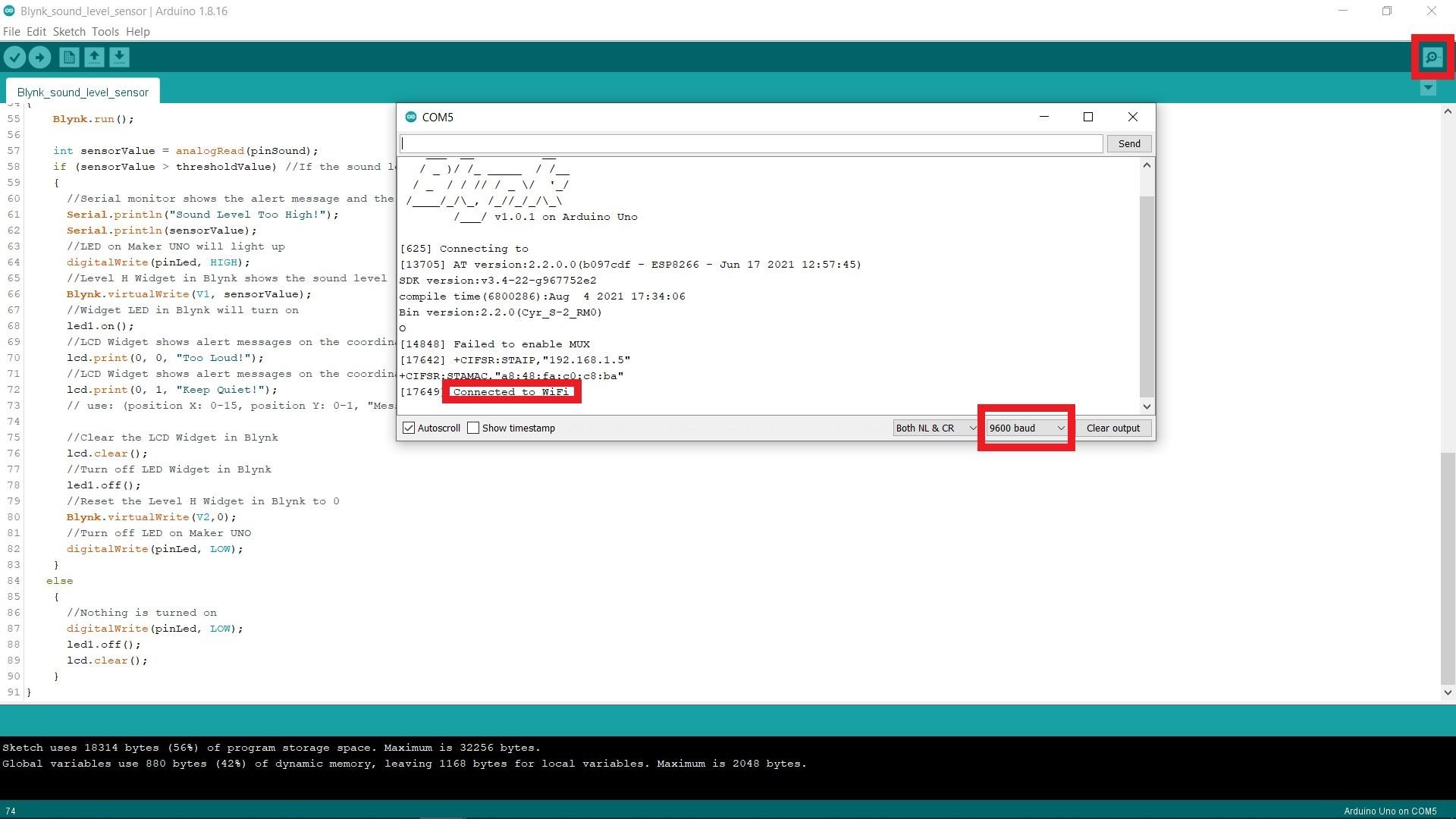
5. If the connection is successful, try to make some noise and if the sound level exceeds the threshold value, you will see the serial monitor and your Blynk project notifying you with the alert message and the sound level value.


Hope you learned how to use Grove WiFi 8266 module with Arduino. Thank you.
You are encouraged to further improve the code for higher efficiency and more advanced applications.
Hardware Components
 -11%
-11%Grove - Sound Sensor
$6.23 $7.00 $6.23
x 1 unit(s)

Grove Base Shield V2
$7.25 $7.25
x 1 unit(s)

Maker UNO: Simplifying Arduino for {Education}
$9.00 $9.00
x 1 unit(s)

Grove WiFi 8266 - IoT for micro:bit and beyond
$6.60 $6.60
x 1 unit(s)
Related Posts
