 International
 Singapore
 Malaysia
 Thailand
 Vietnam
Your shopping cart is empty!
")
HC-05 & HC-05(ZG)
HC-05 & HC-05 (ZG)
There are many Bluetooth modules that look quite similar and sometimes difficult to tell the differences. Deciding what module we have and what firmware is running is the key to finding more information about the Bluetooth modules.
- Markings on the board or breakout board
- Number and type of pins on breakout board
- The type of Bluetooth module model
- The chip used
- Talking to the module
Number and Type of Pins on Breakout Board
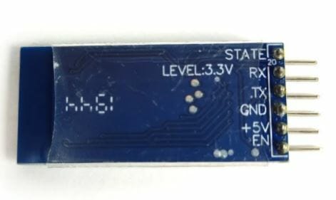
In this article, I will talk about two modules HC-05 & HC-05(ZG), with 6 pins: STATE, RXD, TXD, GND, VCC & EN.
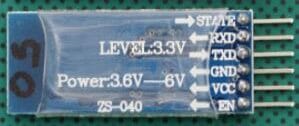 |  |
STATE pin : Shows either the module is connected or not ; Logic LOW for not connected, logic HIGH for connected
RXD/RX pin : UART Serial's Receiver pin
TXD/TX pin : UART Serial's Transmit pin
GND pin : Ground
+5V pin : VCC which is the Positive voltage to power the module.
EN pin : Enabler of the module. It can enable and disable the module.
Bluetooth Standard and Chip
Both HC-05s represent the type of Bluetooth 2.0 or 2.1. On Android devices, all Bluetooth 2.0/2.1 devices should show up in Settings => Bluetooth => Scan for devices. The chips used are the same for HC-05 & HC-05(ZC).
Both HC-05s are Bluetooth 2.0/2.1 EDR devices that have a serial UART layer on top of the Bluetooth. The UART layer makes them easy to use but hides the Bluetooth functions from the user. This is good if all you want is to make 2 things talk to each other. The HC-05 has two modes of operation; AT command mode and transmission mode. When in AT command mode all data received over the serial UART connection is treated as a command, and when in transmission mode, all data received over the serial UART connection is treated as data.
EDR, or Enhanced Data Rate, is a faster PSK modulation scheme capable of transmitting data 2 or 3 times faster than previous versions of Bluetooth. UART, or Universal Asynchronous Receiver-Transmitter, is one of the most used device-to-device communication protocols. In serial communication, data is transferred bit by bit using a single line or wire. In two-way communication, we use two wires for successful serial data transfer.
During in communication mode, if there is an active connection the data is broadcast to the connected device. If not connected, the data disappears into some mysterious void.
The HC-05 can operate as either a slave or master device. Slave devices cannot initiate connections, they can only accept them. Master devices can initiate and (depending on the actual module) sometimes accept them. If you want to use the module with a mobile device such as an Android phone, the phone will be the master device and so the HC-05 will need to be the slave. If you want to link two HC-05s, one will need to be a master and the other one a slave.
Differences of HC-05 & HC-05 (ZG)
1. EN pin is connected to the onboard button.
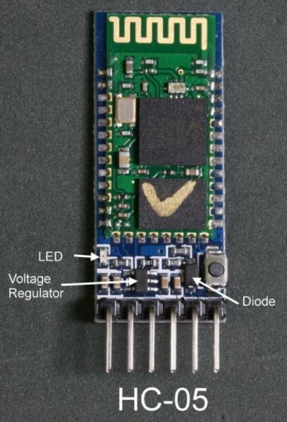
Physical Diagram for HC-05
|
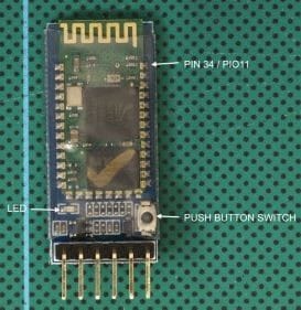
Physical Diagram for HC-05(ZG)
|
AT Command Mode
To put the HC-05 into AT command mode, pin 34/PIO11 has to be HIGH on power up. On the HC-05 breakout board (bottom right corner) there is a small push button switch, this, when closed, connects pin 34/PIO11 to +3.3V, therefore, to put the HC-05 into AT command mode, we can use the button switch.
To enter AT mode using 38400 baud rate :
- Power off the module
- Press and hold the small button switch
- Reapply power while holding the button switch closed
- When LED on, release the button switch
When in AT command mode the LED flash rate will change to 1 second on, 1 second off (or maybe a little slower).
For AT command mode to be fully operational pin 34/PIO11 should be kept HIGH but this is not possible when using just the push button switch. Some commands do not work when in AT command mode and pin 34 is not HIGH. Therefore, some commands need to close the switch before sending.
To return to communication mode, set pin 34 not HIGH (LOW or floating) and cycle the power to the module.
The Wavesen 2010 firmware has a feature that allows it to enter a kind of mini AT mode at the user-settable communications baud rate. In this mode not all commands work, “AT+NAME?” being one of them. Therefore, this mode is not recommended to use the full 38400 AT command mode.
To enter the mini AT command mode, power on the module first and then close the button switch. The LED flash does not change.
HC-05 : Basic Specs
- Bluetooth 2.0 EDR
- Based on the CSR BC417 chip
- Firmware is VERSION: 2.0-20100601 which is by Wavesen.
- Can be a slave or a master device
- Has 2 modes: AT mode and communication mode.
Default baud rate for AT mode is 38400
Default baud rate for communication is 9600
- AT commands can be either lowercase or uppercase
- AT commands require “\r\n” line endings
Conclusion
Overall, both HC-05s contain the same function and firmware. The only difference is the EN pin is connected to the onboard button for HC-05 while the EN pin is not connected to the onboard button for HC-05(ZG). Based on my findings, most users are likely to choose HC-05 compared to HC-05(ZG) as it has a greater advantage. But, these two Bluetooth modules have the same specs, functions and also the firmware.