Introduction
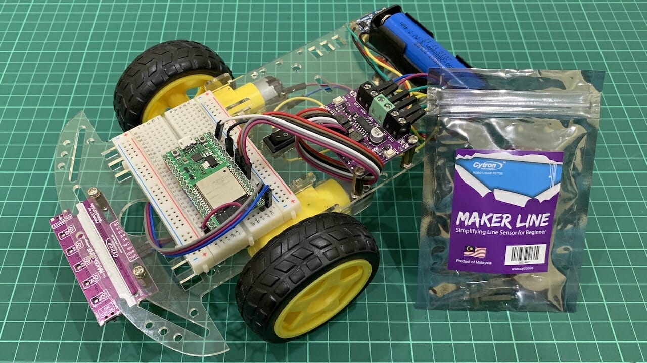
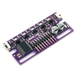
Last week I have shared Raspberry Pi Line Following Robot with Maker Line tutorial. This time I would like to try another 3.3V controller which is ESP32. Plus, instead of using digital pins, I will use analog signal from Maker Line and implement simple PD (proportional and derivative) technique to control mobile robot. Before we start, I recommend you to understand the basic of line following robot. You can refer to this tutorial:
Video
This video is about ESP32 PD line following robot with Maker Line sensor.
Hardware Preparation
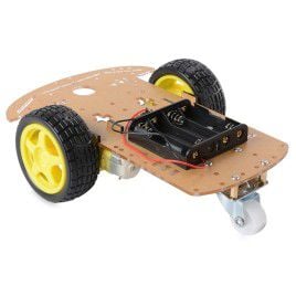
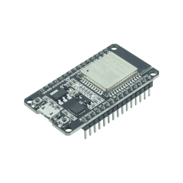
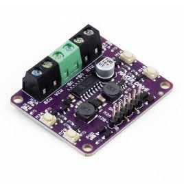
This is the list of items used in the video.
Wiring connection table.
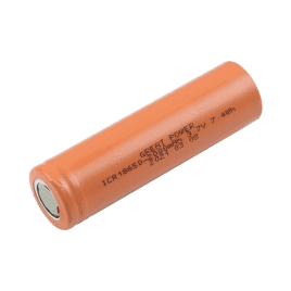
18650 BATTERY | CHARGER MODULE | MAKER DRIVE | DC MOTOR | NODE32 LITE | MAKER LINE |
Positive | B+ | ||||
Negative | B- | ||||
OUT+ | VB+ | ||||
OUT- | VB- | ||||
M1A Terminal | Left Motor | ||||
M1B Terminal | Left Motor | ||||
M2A Terminal | Right Motor | ||||
M2B Terminal | Right Motor | ||||
5V | RAW | ||||
GND | GND | GND | |||
M1A Pin | GPIO33 | ||||
M1B Pin | GPIO25 | ||||
M2A Pin | GPIO26 | ||||
M2B Pin | GPIO27 | ||||
3.3V | VCC | ||||
GPIO36 | AN |
Sample Program
This is Arduino sample code for ESP32 PD line following robot with Maker Line. Please install ESP32 package in order to upload this code into your board. You may need to tune the gain (try and error) based on your hardware.
#define MAKERLINE_AN A0 | |
#define M1A 33 | |
#define M1B 25 | |
#define M2A 26 | |
#define M2B 27 | |
#define PWM_FREQUENCY 1000 | |
#define PWM_RESOLUTION 8 | |
#define M1A_PWM_CHANNEL 0 | |
#define M1B_PWM_CHANNEL 1 | |
#define M2A_PWM_CHANNEL 2 | |
#define M2B_PWM_CHANNEL 3 | |
#define MAX_SPEED 255 | |
int adcMakerLine = 0; | |
int adcSetPoint = 0; | |
int proportional = 0; | |
int lastProportional = 0; | |
int derivative = 0; | |
int powerDifference = 0; | |
int motorLeft = 0; | |
int motorRight = 0; | |
unsigned long currentMillis = 0; | |
unsigned long previousMillis = 0; | |
const int interval = 10; | |
void setup() | |
{ | |
pinMode(MAKERLINE_AN, INPUT); | |
analogReadResolution(10); | |
ledcSetup(M1A_PWM_CHANNEL, PWM_FREQUENCY, PWM_RESOLUTION); | |
ledcSetup(M1B_PWM_CHANNEL, PWM_FREQUENCY, PWM_RESOLUTION); | |
ledcSetup(M2A_PWM_CHANNEL, PWM_FREQUENCY, PWM_RESOLUTION); | |
ledcSetup(M2B_PWM_CHANNEL, PWM_FREQUENCY, PWM_RESOLUTION); | |
ledcAttachPin(M1A, M1A_PWM_CHANNEL); | |
ledcAttachPin(M1B, M1B_PWM_CHANNEL); | |
ledcAttachPin(M2A, M2A_PWM_CHANNEL); | |
ledcAttachPin(M2B, M2B_PWM_CHANNEL); | |
Serial.begin(115200); | |
Serial.println("ESP32 PD Line Following Robot with Maker Line"); | |
// Place robot at the center of line | |
adcSetPoint = analogRead(MAKERLINE_AN); | |
delay(2000); | |
} | |
void loop() | |
{ | |
currentMillis = millis(); | |
if (currentMillis – previousMillis > interval) { | |
previousMillis = currentMillis; | |
adcMakerLine = analogRead(MAKERLINE_AN); | |
if (adcMakerLine < 51) { // Out of line | |
robotMove(0, 0); | |
} | |
else if (adcMakerLine > 972) { // Detects cross line | |
robotMove(MAX_SPEED-25, MAX_SPEED-25); | |
} | |
else { | |
proportional = adcMakerLine – adcSetPoint; | |
derivative = proportional – lastProportional; | |
lastProportional = proportional; | |
powerDifference = (proportional * 1.5) + (derivative * 5); | |
if (powerDifference > MAX_SPEED) { | |
powerDifference = MAX_SPEED; | |
} | |
if (powerDifference < -MAX_SPEED) { | |
powerDifference = -MAX_SPEED; | |
} | |
if (powerDifference < 0) { | |
motorLeft = MAX_SPEED + powerDifference; | |
motorRight = MAX_SPEED; | |
} | |
else { | |
motorLeft = MAX_SPEED; | |
motorRight = MAX_SPEED – powerDifference; | |
} | |
robotMove(motorLeft, motorRight); | |
Serial.print("ADC:\t"); | |
Serial.print(adcMakerLine); | |
Serial.print("\tMotor Left:\t"); | |
Serial.print(motorLeft); | |
Serial.print("\tMotor Right:\t"); | |
Serial.println(motorRight); | |
} | |
} | |
} | |
void robotMove(int speedLeft, int speedRight) | |
{ | |
speedLeft = constrain(speedLeft, –255, 255); | |
speedRight = constrain(speedRight, –255, 255); | |
if (speedLeft > 0) { | |
int speedL = map(speedLeft, 0, 255, 255, 0); | |
ledcWrite(M1A_PWM_CHANNEL, speedL); | |
ledcWrite(M1B_PWM_CHANNEL, 255); | |
} | |
else { | |
int speedL = map(speedLeft, –255, 0, 0, 255); | |
ledcWrite(M1A_PWM_CHANNEL, 255); | |
ledcWrite(M1B_PWM_CHANNEL, speedL); | |
} | |
if (speedRight > 0) { | |
int speedR = map(speedRight, 0, 255, 255, 0); | |
ledcWrite(M2A_PWM_CHANNEL, speedR); | |
ledcWrite(M2B_PWM_CHANNEL, 255); | |
} | |
else { | |
int speedR = map(speedRight, –255, 0, 0, 255); | |
ledcWrite(M2A_PWM_CHANNEL, 255); | |
ledcWrite(M2B_PWM_CHANNEL, speedR); | |
} | |
} |
Thank You
References:
- ESP32 Pinout References
- Maker Line Datasheet
- Maker Drive Datasheet
Thanks for reading this tutorial. If you have any technical inquiry, please post at Cytron Technical Forum.