International
 Singapore
 Malaysia
 Thailand
 Vietnam
Your shopping cart is empty!

Let’s Arduino Control Your SmartDriveDuo-10
- muhammadzaihanif_
- 13 Mar 2017
- 850
Cytron’s 1st dual-channel smart motor driver is ready! SmartDriveDuo10 is a smart brushed motor driver that supports two channels, each up to 10A continuous current. With this driver, building a combat/sumo robot becomes easy, simply get a motor, some wheels, a proper battery, an RC controller, and connect them all to the MDDS10 – and you have a robot! Please check the User’s Manual for details. As for those still asking how to control MDDS10 with Arduino (maybe they want to make their robot smarter?), this tutorial will help you achieve exactly that, because everything is possible with Arduino. The MDDS10 can run in several modes each with their own programming methods. This tutorial will show you how to write the same functions in the 3 more common modes. 1. PWM mode: Independent Both (0b10110100) 2. Serial Simplified: Set the baud rate to 9600 (0b11001100) 3. Serial Packetized: Set ID to 0 (0b11100000)
- Program your Arduino with the following codes. Then disconnect Arduino from the USB.
/* This example shows how to control MDDS10 in Serial Simplified with Arduino. Set MDDS10 input mode to 0b11001100 Serial data (8-bits): 0bMDSSSSSS M: Select motor, 0 for left, 1 for right. D: Direction, 0 for CW, 1 for CCW. SSSSSS: Motor speed. Example: Value in Decimal 0 or 64 - motor LEFT stop. 63 - motor LEFT full forward. 127 - motor LEFT full reverse. 128 or 192 - motor RIGHT stop. 191 - motor RIGHT full forward. 255 - motor RIGHT full reverse. Reference Tutorial: - Let's Arduino Control Your SmartDriveDuo-10 Related Products: - SmartDriveDuo-10: c-93-dc-motor-driver/p-mdds10 - CT UNO: p-ct-uno - DC Brush Motors: c-84-dc-motor - LiPo Battery: c-87-power/c-97-lipo-rechargeable-battery-and-charger URL: */ #includeSoftwareSerial MDDS10Serial(2, 3); // RX (not use), TX void setup() { MDDS10Serial.begin(9600); // Initialize serial delay(5000); // Delay for 5 seconds. } void loop() { MDDS10Serial.write(32); // Motor left start moving with half speed for 2s. delay(2000); MDDS10Serial.write(120); // Motor left move to another direction with half speed for 2s. delay(2000); MDDS10Serial.write((byte)0); // Motor left stop. delay(1000); // Delay for 1s. MDDS10Serial.write(160); // Motor right start moving with half speed for 2s. delay(2000); MDDS10Serial.write(224); // Motor right move to another direction with half speed for 2s. delay(2000); MDDS10Serial.write(128); // Motor right stop. delay(1000); // Delay for 1s. } - Set switch mode to 0b11001100.
- Connect all wires as shown as below and last connect the battery.
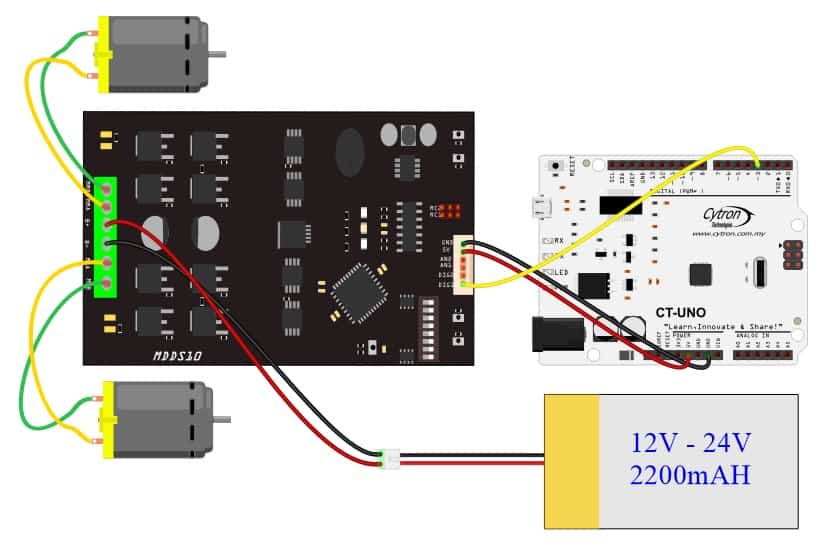
- Once the MDDS10 and Arduino is powered up (all connection complete), both motor will start running alternately.
- Program your Arduino with the following codes. Then disconnect Arduino from the USB.
/* * This example shows how to control MDDS10 in Serial Packetized with Arduino. * Set MDDS10 input mode to 0b11100000 * * Serial Packet: * 1st byte: Header. * 2nd byte: Channel & Address. * 3rd byte: Speed & Direction. * 4th byte: Checksum = 1st byte + 2nd byte + 3rd byte. * * For more information, please refer to MDDS10 User's Manual * https://docs.google.com/document/d/1ECKsH1WfgZLomwFoPQ8PlkUzVEm88A6Sup9X0wDBHKA/view * * Reference Tutorial: * - Let's Arduino Control Your SmartDriveDuo-10 * * Related Products: * - SmartDriveDuo-10: c-93-dc-motor-driver/p-mdds10 * - CT UNO: p-ct-uno * - DC Brush Motors: c-84-dc-motor * - LiPo Battery: c-87-power/c-97-lipo-rechargeable-battery-and-charger * * URL: */ #include
SoftwareSerial MDDS10Serial(2, 3); // RX (not use), TX void setup() { MDDS10Serial.begin(9600); // Initialize serial delay(2000); // Delay for 2 seconds. MDDS10Serial.write(85); // Dummy byte for auto baudrate. delay(3000); // Delay for 3 seconds. } void loop() { // Controlling left motor, direction CW MDDS10Serial.write(85); // 1st byte: Header. MDDS10Serial.write((byte)0); // 2nd byte: Channel = left & Address = 0. MDDS10Serial.write(63); // 3rd byte: Speed = half & Direction = CW. MDDS10Serial.write(85 + 63); // 4th byte: Checksum = 1st byte + 2nd byte + 3rd byte. delay(2000); // Controlling left motor, direction CCW MDDS10Serial.write(85); // 1st byte: Header. MDDS10Serial.write((byte)0); // 2nd byte: Channel = left & Address = 0. MDDS10Serial.write(192); // 3rd byte: Speed = half & Direction = CCW. MDDS10Serial.write(85 + 192); // 4th byte: Checksum = 1st byte + 2nd byte + 3rd byte. delay(2000); // Stop left motor MDDS10Serial.write(85); // 1st byte: Header. MDDS10Serial.write((byte)0); // 2nd byte: Channel = left & Address = 0. MDDS10Serial.write(127); // 3rd byte: Speed = 0. MDDS10Serial.write(85 + 127); // 4th byte: Checksum = 1st byte + 2nd byte + 3rd byte. delay(1000); // Delay for 1s. // Controlling right motor, direction CW MDDS10Serial.write(85); // 1st byte: Header. MDDS10Serial.write(8); // 2nd byte: Channel = right & Address = 0. MDDS10Serial.write(63); // 3rd byte: Speed = half & Direction = CW. MDDS10Serial.write(85 + 8 + 63); // 4th byte: Checksum = 1st byte + 2nd byte + 3rd byte. delay(2000); // Controlling right motor, direction CCW MDDS10Serial.write(85); // 1st byte: Header. MDDS10Serial.write(8); // 2nd byte: Channel = right & Address = 0. MDDS10Serial.write(192); // 3rd byte: Speed = half & Direction = CCW. MDDS10Serial.write(85 + 8 + 192); // 4th byte: Checksum = 1st byte + 2nd byte + 3rd byte. delay(2000); // Stop right motor MDDS10Serial.write(85); // 1st byte: Header. MDDS10Serial.write(8); // 2nd byte: Channel = right & Address = 0. MDDS10Serial.write(127); // 3rd byte: Speed = 0. MDDS10Serial.write(85 + 8 + 127); // 4th byte: Checksum = 1st byte + 2nd byte + 3rd byte. delay(1000); // Delay for 1s. } - Set switch mode to 0b11100000.
- Connect all wires as shown as below and last connect the battery.
- Once the MDDS10 and Arduino are powered up (all connections complete), both motors will start running alternately.