 International
 Singapore
 Malaysia
 Thailand
 Vietnam
Your shopping cart is empty!

SK1632 Tutorial, and Introduction to MPLAB's Harmony
- Nursyamimi
- 16 Dec 2015
- 455
SK1632 Tutorial and Introduction to MPLAB’s Harmony
Author: Ng Yong Han
INTRODUCTION:
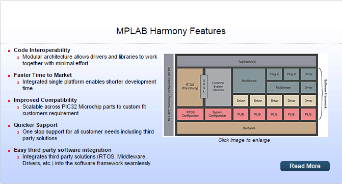
Recently, Microchip has added a new firmware development platform for PIC32, which is called MPLAB Harmony.Here is the summary of the features of the MPLAB Harmony:
In order to use the MPLAB Harmony, you will need:
- MPLAB X IDE 3.15 (Install the IDE first!)
- MPLAB XC32 1.40
- MPLAB Harmony 1.06
- and finally, MPLAB Harmony Configurator Tool 1.07
After installing the MPLAB Harmony, you install the Configurator tool by going to the Tools -> Plugins.
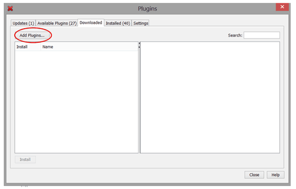
Click on the “Add Plugins” button.
In the Add Plugins menu, you must go to the “C:\Microchip\Harmony\v1_06\utilities\mhc” [where you install the Harmony] and select “com-microchip-mplab-modules-mhc.chm”.
Click on OPEN if you have selected the plugin.
Before proceeding to create your new project, make sure you grab the SK1632 and the PIC32MX250F128B-I/SP microcontroller from the Cytron store!
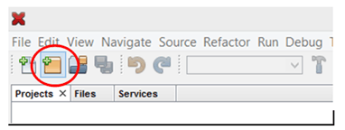
TO CREATE A NEW PROJECT:
Click on the button in the red circle:
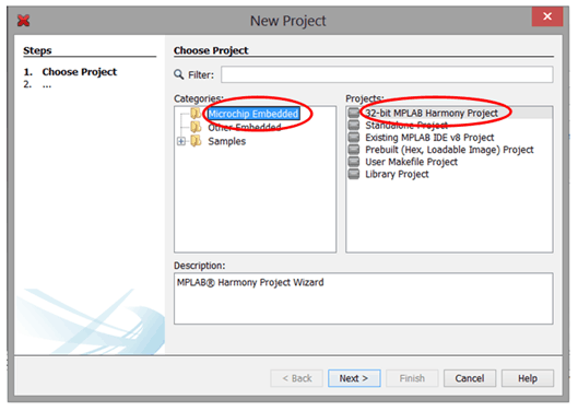
Then, in the “New Project” box, click on “Microchip Embedded”, and then the “32-bit MPLAB Harmony Project”. Then click “Next >”:
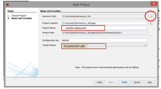
In the next step, you need to provide the Harmony path. Click the little folder icon in the red circle, and then select the location of the Harmony as shown in the following picture:
The “Project Location” and the “Project Path” will be generated automatically when you provide the correct Harmonypath. Enter the “sk1632-helloworld” in the “Project Name”, select the “PIC32MX250F128B” in the “Target Device” and then press “Finish” to proceed.
After you have pressed Finish, wait for the MPLAB X to load the required Harmony tools. Now the thing that you should do is to configure your microcontroller in your SK1632 for it to run!
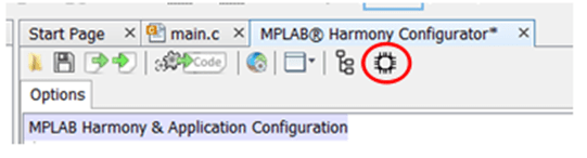
To launch MPLAB Harmony Configurator, click on:
![]()
CONFIGURING THE PERIPHERALS:
On the center of the IDE, collapse a few menu items as shown, check the box on “Use Clock System Service?”, and click “Execute” in the “Launch Clock Configurator”.
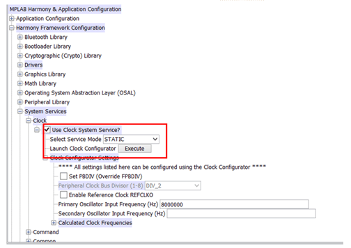
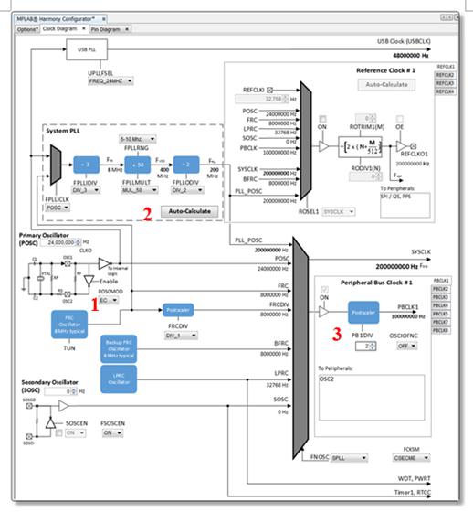
In order for the microcontroller to function you must configure the oscillator, and the Clock Configurator is a chart showing the parts of the oscillator:
(Full chart source: http://microchip.wikidot.com/harmony:mhc-overview)
1) Select “XT” in the “POSCMOD”. Make sure the Primary Oscillator (POSC) value is “8,000,000 Hz” [since we are using 8MHz crystal! ].
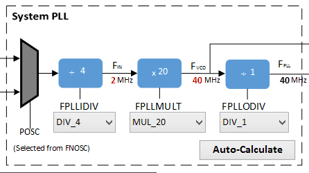
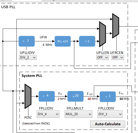
2) You must select these options according to the datasheet of the microcontroller and the 40MHz speed:
- FPLLDIV = DIV_4
- FPLLMULT = MUL_20
- FPLLODIV = DIV_1
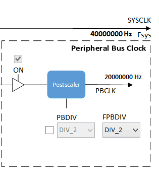
3) Then, finally, make sure that the Peripheral Bus (PB) is 20MHz. Put “2” in the FPBDIV:
4) Finally, USB is not used in the module, but we still need to configure it a bit as shown in the following diagram (it is above the “System PLL”):
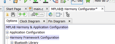
So we are done setting the oscillator, but we need to activate a few peripherals in the microcontroller. Let us take thefirst simple one for the tutorial which is the “Timer”. Go back to the “Options” in the MPLAB Harmony Configurator menu:
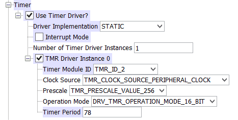
In the configuration, select Harmony Framework Configuration->Timer, and a few options are shown there. Follow exactly the options in the picture:
And now, you need to see if it’s running too! A blinking LED at a rate of half-second is good enough to get you started! But we need to configure the GPIO on the SK1632 first. Click on the Pin Settings in the menu:
Here you see all the pins on that microcontroller, and lists out the functions of the individual pins:
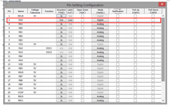
In the RA0 (the orange LED in SK1632), click on the “In” on the “Direction (TRIS)” column to change to the “Out”. As usual, the RA0 is now an output. Oh, and also, change the “Mode (ANSEL)” to “Digital”.
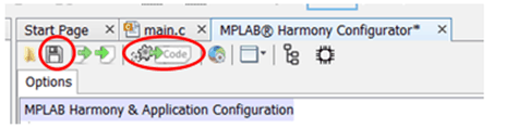
When you are done setting all the peripherals and oscillator configuration, click “Save” [the diskette icon] and then “Generate Code” [with two gears]:
Again, wait a moment for MPLAB X to configure the microcontroller. You can return to the MPLAB Harmony Configurator if you need to activate peripherals or change the oscillator settings in the microcontroller.
MAIN PROGRAM:
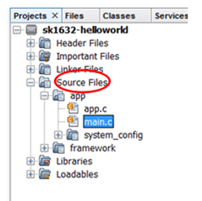
Now, on your left of the IDE, click on the “Source files”, then “App”, then “main.c”. You are now editing “main.c”:
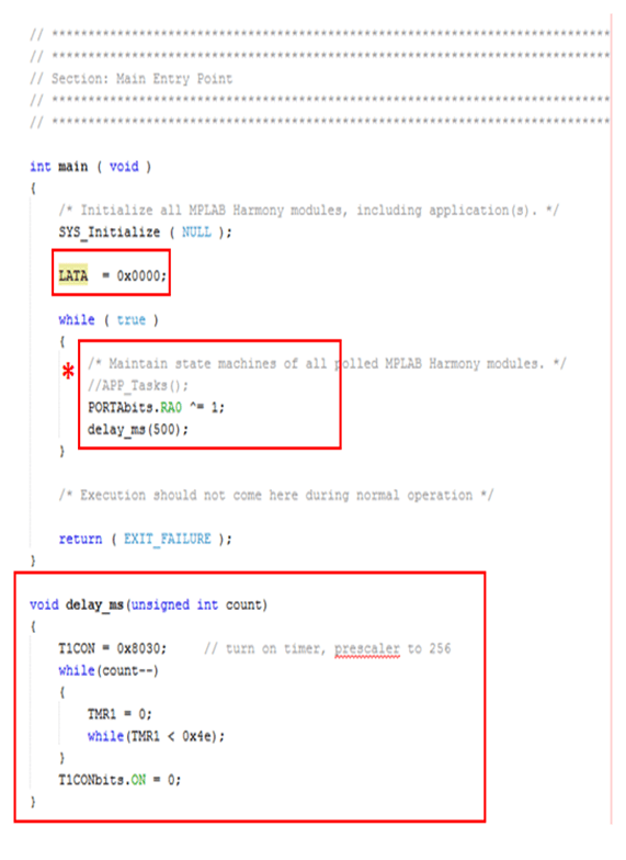
For a very simple project, we add the simple, straightforward delay code using a Timer we have just configured [1]. Add the function prototype “void delay_ms” just after the includes:
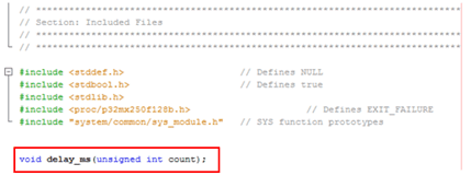
In the main() function,
- Add the “LATA = 0x0000”.
- In the box with the asterisk (*) comment out the “APP_Tasks()”, add the “PORTAbits.RA0 ^= 1, and delay_ms(500)”.
- After the main() function, add the delay_ms() function as shown in the picture.
Save the work. Now take out your SK1632, solder the headers, connect the crystal, and then connect the PICKit3 to the SK1632:
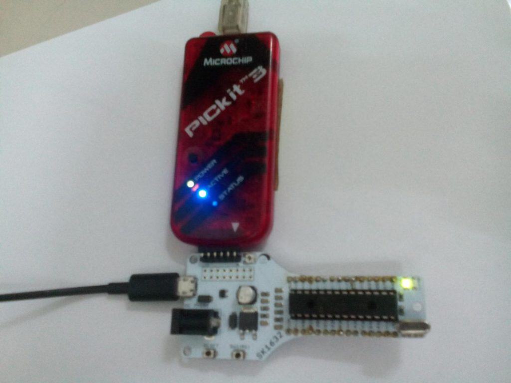
Be sure to connect the USB port to a power bank, or a computer, or a smartphone charger.
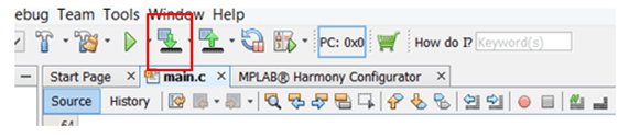
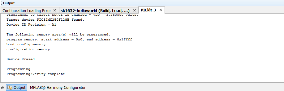
Compile, and copy the program into the SK1632:
Without errors in the compilation, and a successful connection at the PICKit 3 side, you see this and the blinking orange LED per half-second. Congratulations, you have created a SKPIC32 project successfully!
As an exercise, why not change the blinking speed of the LED by pressing the button on the SK1632?
References:
1.) Lucio di Jasio (2008), Programming 32-bit Microcontrollers in C: Exploring the PIC32, Newnes.