ESP8266 Tutorial Part I - Getting Started

ESP8266 Tutorial Part I - Getting Started

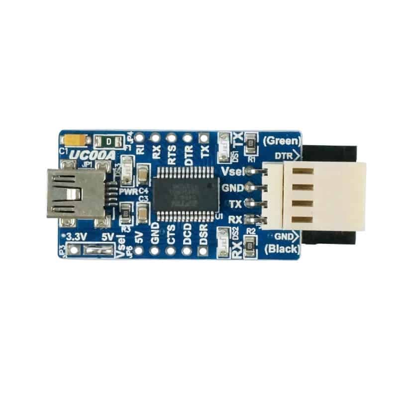
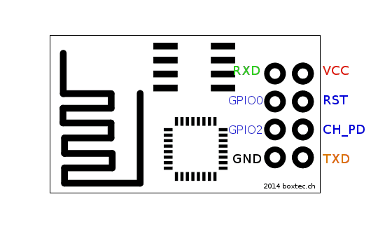
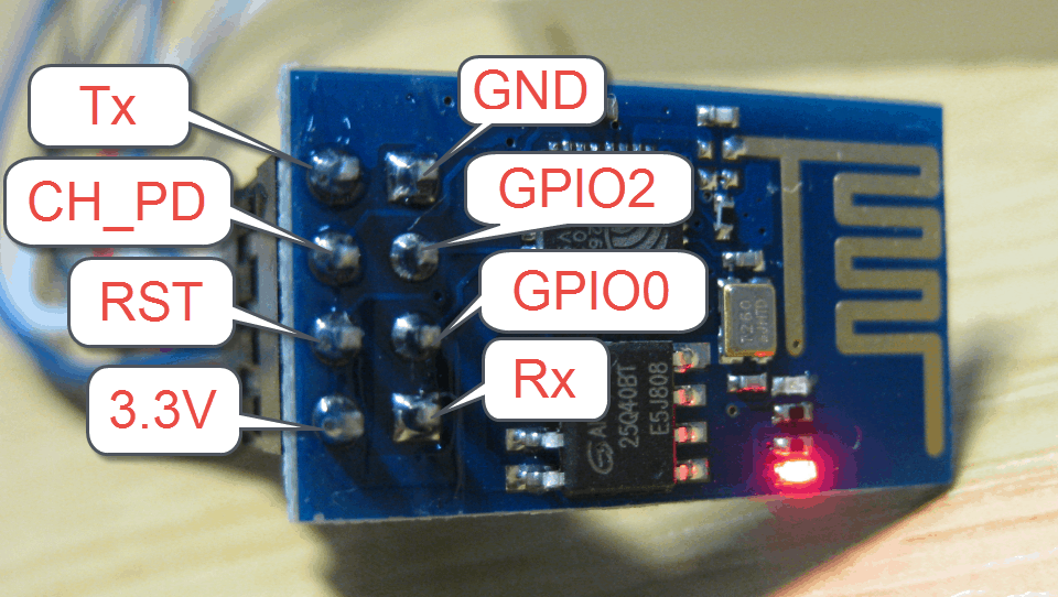
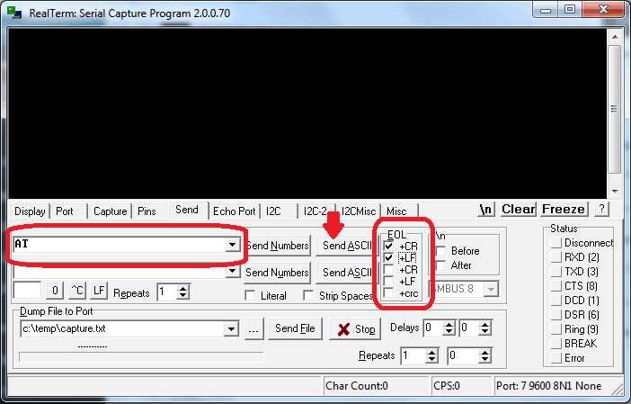
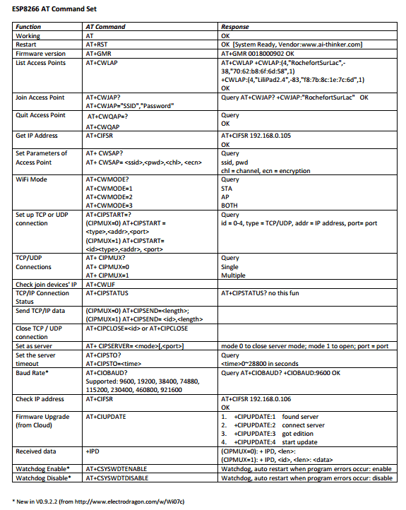
Hello everyone! Cytron Technologies has brought you another small and yet fantastic module: Wifi Serial Transceiver ESP8266!! Don’t under estimate the capabilities of this small module, ever thought about making your own web server in your room, or control your appliances at your house even as you are far away from your home, yet you don’t want to spend a lot to make all these? Good news is, this small amazing module can be low cost solution you are seeking for! Besides that, it is easy to learn and use. Interested? Come, let’s get started. This tutorial will teach you some basics on how to use this module by giving AT command through UART communication.


What is ESP8266 WiFi Module and what can it do?

Self contained system on chip (SoC)

Connects your projects to your WiFi Network

Making your network application

Integration with sensors and other application devices

Supports UART communication

Low cost


Before we get started, let’s see what we need for this tutorial…

Hardware

Software

RealTerm Serial Capture Software

(Please click here for download)

How does ESP8266 WiFi module connect?

Before we get this ESP8266 WiFi module powered up and ready, we have to assemble all necessary hardware all together. Let’s take a closer look on this module and its pinouts.

The picture below shows the basic connection between the ESP8266 WiFi module and other hardware.

ESP8266 WiFi ModuleConnection
VCC+3.3V
GNDGND
RXTX of UART device
TXRX of UART device                    
CH_PD+3.3V
GPIO0NC
GPIO2NC
RSTNC

Note: 

  1. TX and RX serial connections ‘crossover’ is a must: i.e RX pin of ESP8266 module must be connected to TX pin of the other UART device or vice versa. Not crossing over is a common mistake when first hooking up a serial communications device. In this tutorial we are going to connect ESP8266 with USB to UART converter.
  2. ESP8266 is 3.3V compatible only device so don’t try to power up the device directly with power supply more than 3.3V or you will damage the module. Voltage regulator is needed if you  use power supply more than 3.3V.
  3. Make sure your UART device can provide RX and TX signal with +3.3V logic level as well or else a voltage level shifter is needed. Most microcontrollers such as Arduino and PIC provides RX and TX with 5V logic so don’t connect their RX and TX connections directly!
 

Setup time!!

Now let’s start assembling the circuit and power up the module!!

Step 1:

Prepare two sets of male header pins (each with 5 pins) and a USB to UART converter. Use soldering tool to solder them up as shown in the picture. Once finished, the place the USB to UART converter on the breadboard.

Step 2:

Connect the ESP8266 WiFi module with USB to UART converter using male to female jumper. Then connect the rest of the components such as the 3.3V voltage regulator, capacitors, etc. as shown in the picture below.

Step 3:

Slide the slide switch on the USB to UART converter to the position labelled with 3.3V so that RX and TX signals are +3.3V level logic. (Note: USB to UART converter does not come with slide switch, so make sure you solder it on your own)

Step 4:

Connect the USB to UART converter to your computer using USB MiniB cable. Turn on the switch on breadboard to power up the module.

If you can see the red light turned on permanently, while the blue light flashes, it means your module is ready to use!

OK we have done with the hardware setup. Let’s give a try to this module!!

This module supports UART communication, and you can use any serial monitor software to communicate with this module. In this tutorial, we are going to useRealTerm software as communication tool. If you still don’t have this software, click here to download.

Once you have opened the software, you should be seeing a black display screen and few tabs beneath it. Switch to Port tab.

To establish a connection between PC and ESP8266 module, there are a few things you have to take note:

  1. Port
  2. Baudrate
  3. Parity
  4. Data Bits
  5. Stop Bits

Checking the COM Port

Port refers to COM port. Which port we are going to choose depends on which COM port your device (USB to UART converter) is connecting to. To check it out, simply right click My Computer -> Properties -> Device Manager. You can check the COM port your device is connecting at Ports (COM & LPT). In this tutorial, the device is connected to COM7.

Start establishing connection

Default baudrate, parity bit, data bit and stop bit of ESP8266 WiFi module are 9600, None, 8 and 1 respectively. After determining which COM port your device is currently connecting to, begin the setup as below at Port tab.

Baudrate9600
COM(your COM port, COM7 for this tutorial)
ParityNone
Data bits8 bits
Stop bits1 bit

Once finished, click the Open button. You will get a visual that the button is being pressed.

Testing ESP8266

Switch to Send Tab, this is where you start talking to module and tell it what to do. Here we will be giving AT command to this module and the module will respond to each command we entered if the command is correct.

Let’s greet the module by giving some command. First type AT into the textbox, and make sure you check +CR and +LF at EOL category as shown in the picture below. This will automatically add Carriage Return and Line Feed to the whatever we type in textbox before PC send them to the ESP8266.

After you have done, click Send ASCII.

If you receive OK at display screen, congratulations! You have successfully ‘talk’ to the module!! 

More commands to ESP8266!!

Of course ESP8266 is not designed to just give you an ‘OK’. Now it is ready for more commands from you and it will execute the tasks according to the AT commands you have entered. (and of course AT command must be correct). Below is a list of AT commands you can play with ESP8266. (Click here for AT command list pdf file)

Let’s make a simple web server using AT commands!!

Let’s apply some AT commands! We are going to make this ESP8266 into a simple web server. Whoever browses this server will see “Hello World” on the webpage. Let’s try it!

Step 1: Setting working mode

First of all, send AT+CWMODE? to check the ESP8266 module working mode. By default you should be getting response&