 International
 Singapore
 Malaysia
 Thailand
 Vietnam
Your shopping cart is empty!

INTRODUCTION
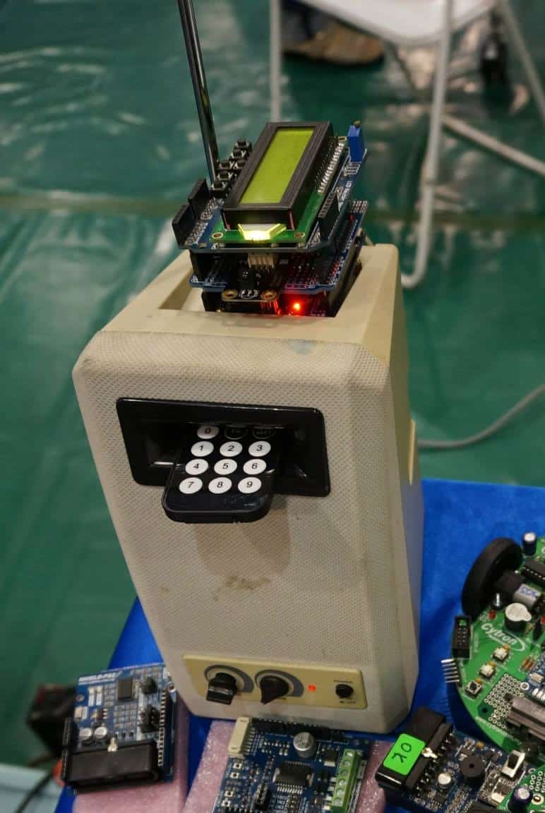
If you happen to be at Singapore Maker Faire and check out our booth or our Cytron FaceBook Page pictures, you might notice that there is a Big Tradition Speaker with Arduino and a Long~~ antenna on top. That’s actually is a DIY FM radio with speaker. It come with a remote control that set with some function so it allow to auto/manual search and save any frequency you like to tune to. It not really a big project, BUT, I would like to say it do create a good experience for a brand new makers to start with.
Let me share with you the simple steps process, source material and how to read and save the FM Freq into Arduino, so next time when you turn it OFF and ON, it’s still there.
COVERED IN THIS TUTORIALS
- Hardware Overview – An overview of the how to identify the power wire of the speaker and connect to Arduino UNO.
- Reading the IR Remote output – Identify the output of the IR remote receiver.
- Example Code – Overview of the library and code in this project, the function on how to save the freq like the Real Radio!!..
SUGGESTED READING
- Remote Control FM Stereo Radio
- Arduino EEPROM Library
- Arduino Wire Library
- TEA5767 Datasheet
- FR02A User Manual
- Rectification
REQUIRED MATERIAL
- FR02A FM Stereo Module
- IR Remote Control Kit
- Arduino UNO
- LCD Keypad Shield
- Cytron Prototype Shield (Optional)
- An Amplifier Speaker
HARDWARE OVERVIEW
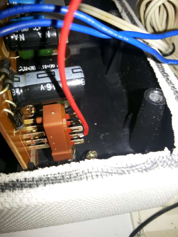
Once upon a time, these big junk speaker have a power cord that connect to 240V AC in order to turn it on. Not like nowaday that the speaker can be power using a single USB cable right? Do you think it don’t seem to make sense that it run this small speaker with 240V AC? Well, try open it up and take a good look and HEY!!, there is a Transformer inside that make this thing work.
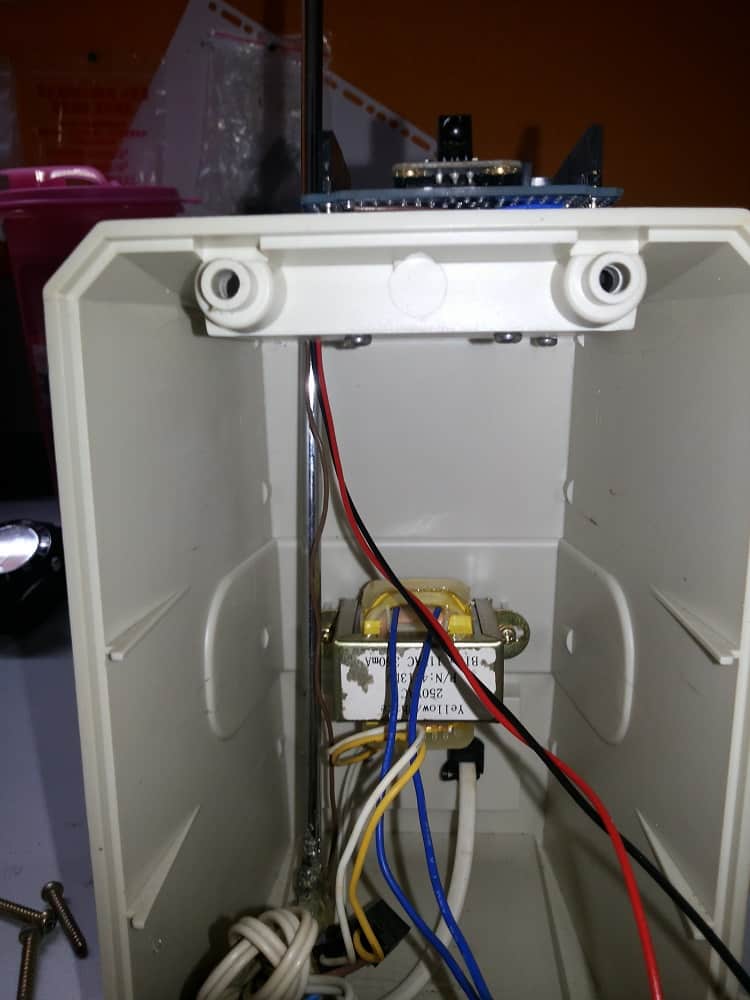
Since the speaker is running in DC and it of course would have AC to DC converter inside the circuit. But, the question is how to identify it??? Let go back to the basic.
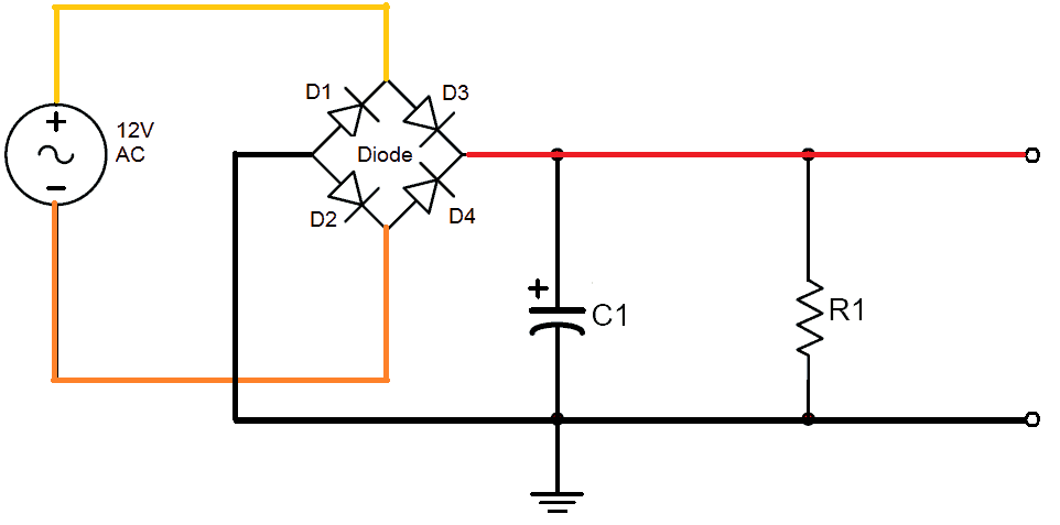
The circuit above shows the shows that the basic of how the AC convert into DC power by using 4 diode and capacitor which known as Rectification. Well in this chart, it shows clearly the input of the 12V AC as well as the DC. output. The Yellow and Orange color wire represent the AC line that goes into the diodes and Red and Black color represent the 12V DC output.
From this circuit, we may see that Anode of (D1 and D2) are connected to GND. While Cathode of (D3 and D4) are 12V DC. This mean if we going to take the out the Dc power, we have to focus on looking for the Input of AC power and the direction of the diode to determine the where is the DC power. The best tools to use in this session here is multimeter where by measuring each diode point to look for positive(+ve) and negative(-ve) 12V. But, be double carefulas we are dealing with the AC power.
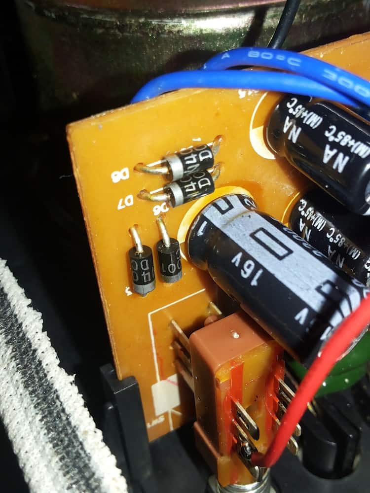
After identify the diodes then the next question would be HOW to measure using multimeter? OR what kind of reading will it give. Let’s See the answer below.
IDENTIFYING WHERE IS THE AC
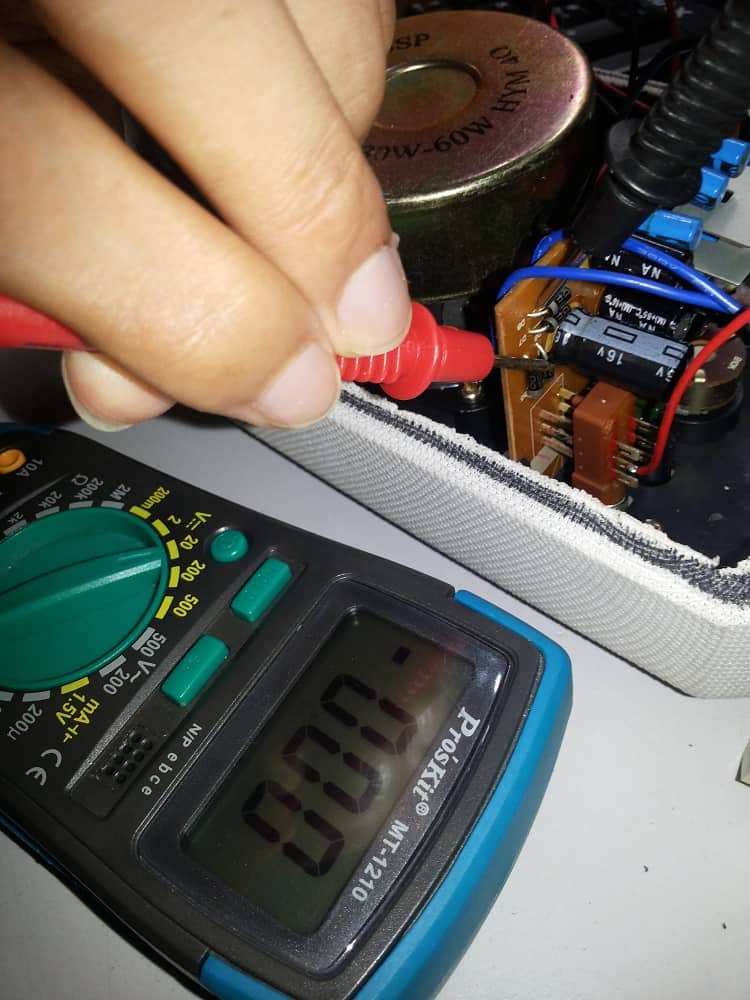
If you’re measuring AC while your multimeter switch to DC mode, mostly likely you’ll get 0V.
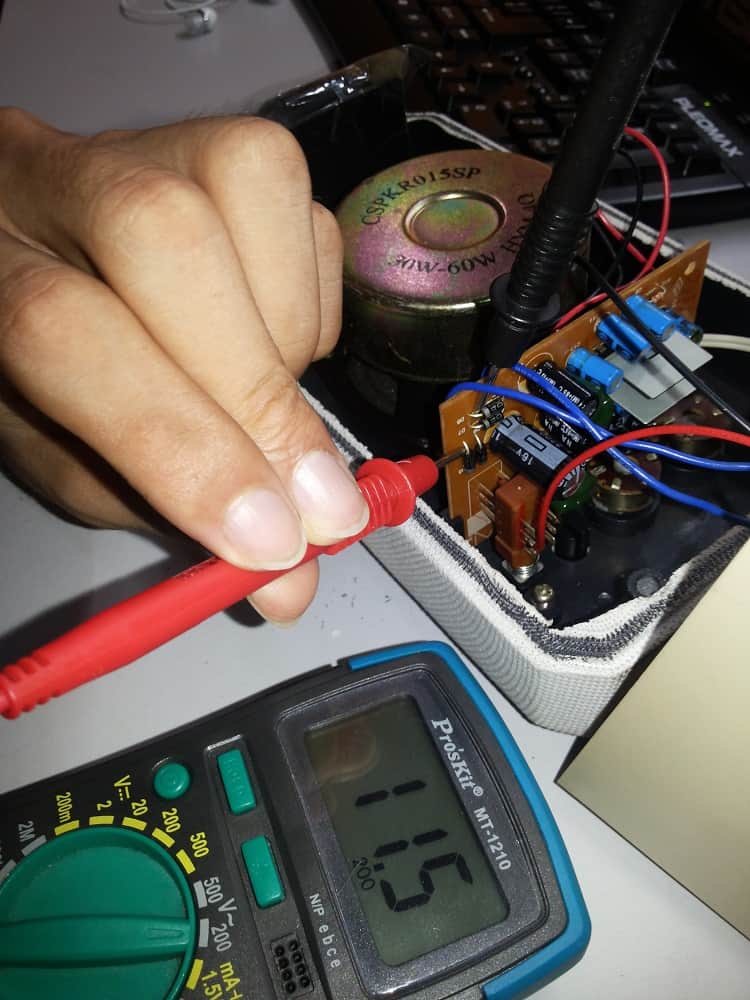
CONFIRM IF THAT IS AN AC INPUT
If you’re measuring AC while multimeter in AC mode, you’ll get a 12V reading back. Now that we have get the location of AC input. Which mean the other side of diode should be DC. But be double confirm is always a good behavior for an engineer so as a maker.
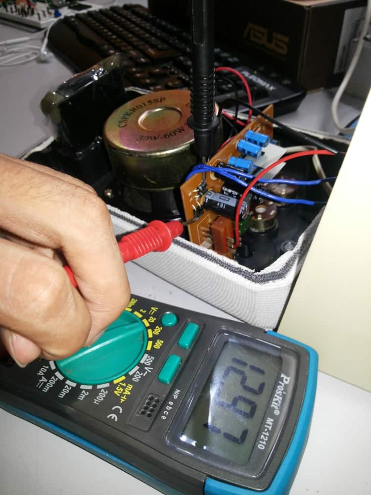
LOOK FOR DC INPUT
Measuring the other side of the diode with multimeter in DC mode, you will get roughly 12V reading back in multimeter. So, IT’S CONFIRMED!!
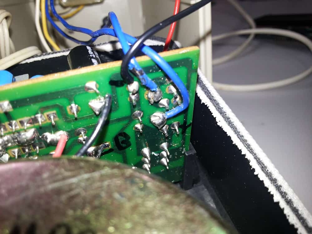
MARK YOUR WORK
Mark it after you identified it so that you won’t forget.
A LITTLE ADD-ON
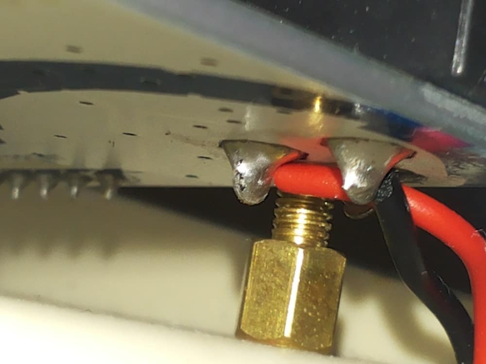
While I’m thinking that I don’t want my Arduino to turn ON once my AC power is power up, But, I would like to turn ON my Arduino together with the speaker. That’s actually very simple because this speaker come with a power button where all you need to do is just connect the DC power line to the power button pin like picture below.
ONE MORE THING…
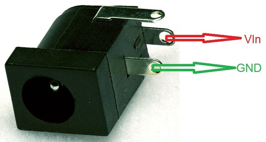
Since the DC power is 12V, it suit my Arduino power input requirement. But make sure that you link the 12V DC back to Arduino. If you link the AC back to Arduino, I should be seeing either the Arduino having a dance because of the 50Hz or it burn out. Next, I would recommend to connect the 12V DC directly to the DC Jack like picture below.
Please make sure where is the Positive(+ve) of the DC Jack using multimeter. Picture below shows that the Positive(+ve) where is connected to.
READING THE IR REMOTE OUTPUT
Many had request the timing diagram for the IR Remote Control from us and we are very sorry that we cannot meet your need because the bad news is we also don’t have one. But, the Good News is, in here I’m going to show how to get the reading from the IR Remote control using Arduino Serial. The steps are below:
- Download IR Remote Arduino Library.
- Extract to your PC. Documents > Arduino > libraries.
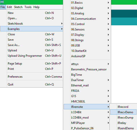
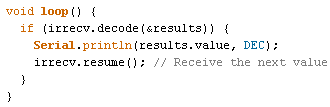
- Open the Arduino IDE. Go to File > Example > IRremote > IRrecvDemo.
- Connect the IR Receiver wire to Digital 11 in Arduino.
- Change the HEX to DEC. (As I’m using Decimal in this project, you may use whatever you want)
- Clock “Upload” and wait until it’s done uploading.
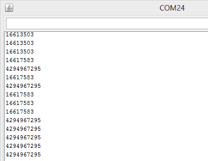
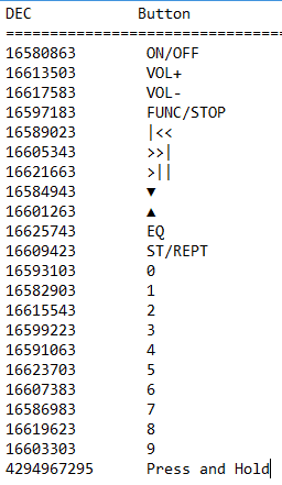
- Click the “Serial Monitor” and press the IR Remote Control button.
EXAMPLE CODE
In here, I’m not going to touch on how to set or search the FM Freq as as this had been explain in the FR02A example code.
In fact, I’m going to talk about how you save the FM Frequency in the Arduino memory or EEPROM permanently until you overwrite it. The example code for this project can be download here.
The code below shows that what will happen when you press or press and hold the number ‘0’. I’ll take this part as example to explain because the same thing will happen to number ‘1’ to ‘9’ as well. Let’s start from the “Orange” box. The code in the box is talking about read the current FM frequency and change the Frequency decimal point. Example from 87.50 to 8750. This step have to add in because the EEPROM only accept Byte. The number after the decimal point will be eliminate.
As for the “Green” box, the code here is to compare the current FM Frequency with the default Frequency which is 8750. If current frequency is not 8750 or below, then change the currently frequency to 8750. This make the button alike your real radio button whereby if the button did not preset the FM frequency, the default is 87.50.
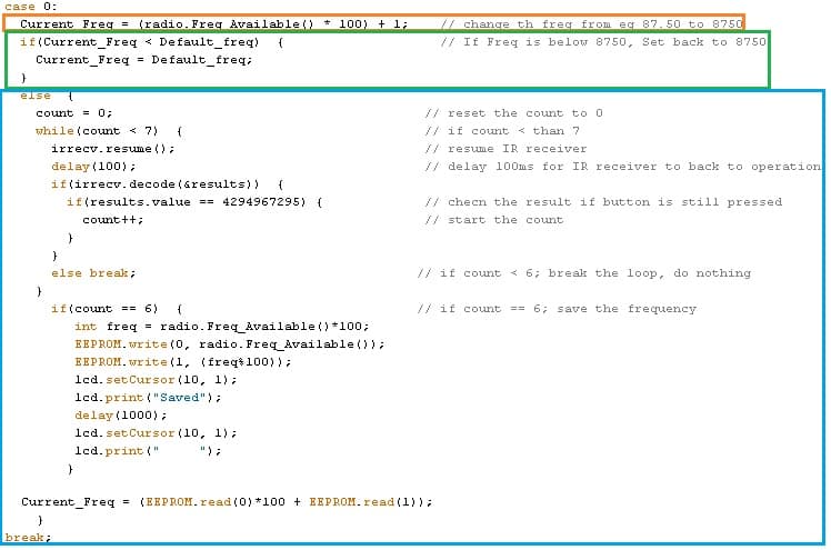
As for the last part, the “Blue” box, is about counting how long you had HOLD the button. I had put it into a simple way where it will start counting from 0 to 6, and when it done the count, save the FM frequency to the EEPORM. Of Course, always start with reset the ocunt back to 0. And resume the IR Remote Receiver and check if the “Press and Hold” decimal code is detected. If yes, then increase the count. If the count is stop below 7, break the whole loop. Nothing happen.
If the count is equal to 6, read the FM Frequency again and change the decimal point. Since the EEPROM only can store the maximum data in Byte, the FM Freq had to separate into 2 and store into EEPROM ‘1’ and EEPROM ‘2’. Example: FM Freq 8750 will be “87” in EEPROM ‘1’ and “50” will be in EEPROM ‘2’. The Lastly, display “Saved” on the LCD screen as indicator.
Of course, always feedback the frequency saved back to the void loop() using EEPROM.read(). That’s it from me. If you have any question, go on and ask in our forum.cytron.com.my. :)