 International
 Singapore
 Malaysia
 Thailand
 Vietnam
Your shopping cart is empty!

Non-looped Maze Solving Robot with MC40A
- Idris Zainal Abidin
- 10 Mar 2014
- 438
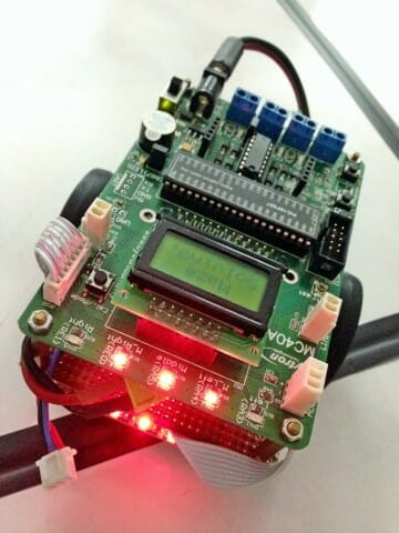
Hi, today I would like to write a tutorial on Non-looped Maze Solving Robot with MC40A. If you still remember the Remote Mobile Robot with XBee-WiFi tutorial, I use the same hardware for this tutorial, except I remove the Xbee WiFi + Xbee Starter Kit, and add LS05A.
THEORY
Maze Solving steps:
1st run – Drive through the maze and find the finish point.
2nd run – Drive through the maze to the finish point with shortest path (not enter the dead path).
Maze Solving technique:
For non-looped maze solving, we can use “left hand on the wall” technique. Imagine walking through a real labyrinth (a human-sized maze built with stone walls) while keeping your left hand on the wall at all times. You’ll turn left whenever possible and only turn right at an intersection if there is no other exit. Sometimes, when you reach a dead end, you’ll turn 180 degrees to the right and start walking back the way you came. Eventually, as long as there are no loops, your hand will travel along each length of wall in the entire labyrinth exactly once, and you’ll find your way back to the entrance.
This “left hand on the wall” algorithm can be expressed into these statement:
IF you can turn left then turn left,
ELSE IF you can continue driving straight then drive straight,
ELSE IF you can turn right then turn right.
IF you are at a dead path then turn back.
Define the path name:
To make the path easier in programming, we can define it as follow,
Left – L
Right – R
Straight – S
Turn back – B
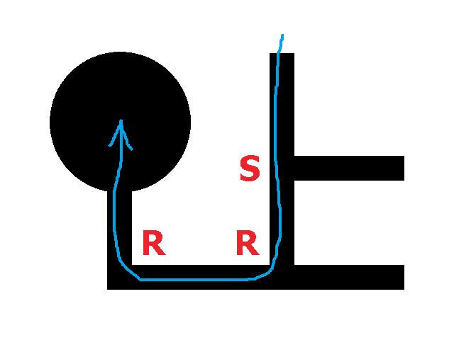
Example: LBLLBSR (This path represent the picture below)
Simplifying the solution:
We can see in the picture above, at the 1st junction the robot should go straight for correct path, so we can simplify the path by substituting LBL to S, and this is the whole list for substitution:
LBL = S
LBR = B
LBS = R
RBL = B
SBL = R
SBS = B
We can try to simplify this path, LBLLBSR.
LBLLBSR = SLBSR
SLBSR = SRR
So the final path optimization is SRR (refer picture below). In other words, as long as ‘B’ exists, the optimization is needed.
To make better understanding, we try another example. Simplify this path LLRBLRLLRLLSBLL.
LLRBLRLLRLLSBLL = LLBRLLRLLSBLL
LLBRLLRLLSBLL = LBLLRLLSBLL
LBLLRLLSBLL = SLRLLSBLL
SLRLLSBLL = SLRLLRL
So the final path optimization is SLRLLRL.
HARDWARE
1. MC40A (link).
2. UIC00B – Programmer (link).
3. SPG10-150K (link).
4. Motor Bracket (link).
5. Castor (link).
6. Battery (link).
SOFTWARE
PROGRAMMING HIGHLIGHT
This robot uses LSS05 line sensor to track the black line. Three middle sensor is used for straight line and most left and right sensor is used to detect the junction. So this is a code for straight line.
if (!senMLeft && senMiddle && !senMRight)
{
  motor(70, 70);
}
else if (senMLeft && senMiddle && !senMRight)
{
  motor(40, 70);
}
else if (!senMLeft && senMiddle && senMRight)
{
  motor(70, 40);
}
else if (senMLeft && !senMiddle && !senMRight)
{
  motor(30, 70);
}
else if (!senMLeft && !senMiddle && senMRight)
{
  motor(70, 30);
}
Once the sensor sense the junction (e.g. T junction), we need to set the robot to choose left junction instead of right. So if the robot sense the right junction first, robot need to wait a little bit for the left sensor to detect the junction (if present).
if (senRight && !senLeft)
{
  motor(30, 30);
  for (i = 0; i < 200; i++)
  {
    if (senLeft) break;
    delayMs(1);
  }
  if (!senLeft)
  {
    motor(0, 0);
    delayMs(200);
    if (!senMiddle)
    {
      dir = ‘R’;
      motor(30, -30);
      while (!senRight);
      while (!senMRight);
      motor(0, 0);
      delayMs(200);
    }
    else dir = ‘S’;
  }
}
if (senLeft)
{
  motor(30, 30);
  delayMs(200);
  motor(0, 0);
  delayMs(200);
  dir = ‘L’;
  motor(-30, 30);
  while(!senLeft);
  while(!senMLeft);
  motor(0, 0);
  delayMs(200);
}

if (!senLeft && !senMLeft && !senMiddle && !senMRight && !senRight)
{
  motor(0, 0);
  delayMs(200);
  dir = ‘B’;
  motor(30, -30);
  while(!senRight);
  while(!senMRight);
  motor(0, 0);
  delayMs(200);
}
If robot enter the dead path, the robot should do a U turn.
if (!senLeft && !senMLeft && !senMiddle && !senMRight && !senRight)
{
  motor(0, 0);
  delayMs(200);
  dir = ‘B’;
  motor(30, -30);
  while(!senRight);
  while(!senMRight);
  motor(0, 0);
  delayMs(200);
}
Every time robot meet the junction or dead path, it need to memorize the path, so in this case we store the path name into the array (e.g. ‘S’, ‘R’, ‘L’ and ‘B’). Don’t forget, we can to simplify the path by do a substitution formula. To ease, when the robot do a U turn, we can simplify the path after the robot meet the next junction. This is a code of path simplification.
if (!memcmp(“LBL”, &string, 3)) path[pathLength] = ‘S’;
else if (!memcmp(“LBR”, &string, 3)) path[pathLength] = ‘B’;
else if (!memcmp(“LBS”, &string, 3)) path[pathLength] = ‘R’;
else if (!memcmp(“RBL”, &string, 3)) path[pathLength] = ‘B’;
else if (!memcmp(“SBL”, &string, 3)) path[pathLength] = ‘R’;
else if (!memcmp(“SBS”, &string, 3)) path[pathLength] = ‘B’;
Last but not least, when the robot sense the finish point (all 5 sensor detect the black line), the robot will stop and finish.
if (senLeft && senMLeft && senMiddle && senMRight && senRight)
{
  motor(0, 0);
  beep(3, 300);
  pathTotal = pathLength;
  lcdGoto(1, 6);
  lcdNumber(pathTotal, DEC, 2);
  break;
}
Non-looped Maze Solving Robot source code (download).