Your shopping cart is empty!
RH2T Magazine Vol 2, Dec 2009
STEPPER MOTORS OPERATE DIFFERENTLY FROM NORMAL DC MOTORS, WHICH ROTATE WHEN VOLTAGE IS APPLIED TO THEIR TERMINALS.
An Overview
Stepper motors were developed in the early 1960’s as a low cost alternative to position servo systems in the emerging computer peripheral industry. The main advantage of stepper motors is that they can achieve accurate position control without the requirement for position feedback. In other words, they can run “open-loop”, which significantly reduces the cost of a position control system. A stepper motor converts electronic pulses into proportionate mechanical movement. Each revolution of the stepper motor’s shaft is made up of a series of discrete individual steps. A step is defined as the angular rotation produced by the output shaft each time the motor receives a step pulse. Each step causes the shaft to rotate a certain number of degrees. The size of this step is dependent on the teeth arrangement of the motor, but a common value is 1.8 degrees, or 200 steps per revolution.
Stepper Motors vs. Other Motors
1. Brushless
– Stepper motors are brushless. Motors with contact brushes create sparks, undesirable in certain environments.
2. Holding torque
– Stepper motors have very good low speed and holding torque. Stepper motors are usually rated in terms of their holding torque and can even hold a position (to a lesser degree) without power applied, using magnetic ‘detent’ torque.
3. Open-loop positioning
– Stepper motors can run ‘open-loop’ without the need for any kind of encoder to determine the shaft position. Compared to servos (Closed loop systems- systems that feed back position information), stepper motors are very easy to control. The position of the shaft is guaranteed as long as the torque of the motor is sufficient for the load, under all its operating conditions.
4. Load independent
– The rotation speed of a stepper is independent of load, provided it has sufficient torque to overcome slipping. The higher RPM a stepper motor is driven, the more torque it needs, so all stepper motors eventually start slipping at some RPM. Slipping is usually a disaster for steppers, because the position of the shaft becomes unknown. For this reason, software usually keeps the stepping rate within a maximum top rate. In applications where a known RPM is needed under a varying load, steppers can be very handy.
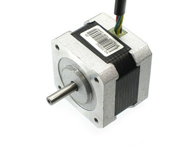
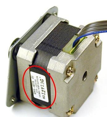
A typical 2-phase unipolar stepper motor
Stepper Motor Characteristics
Stepper motors are constant power devices. As motor speed increases, torque decreases. The torque curve may be extended by using current limiting drivers and increasing the driving voltage.
Steppers exhibit more vibration than other motor types, as the discrete step tends to snap the rotor from one position to another. This vibration can become very bad at some speeds and can cause the motor to lose torque. The effect can be mitigated by accelerating quickly through the problem speed range, physically damping the system, or using a micro-stepping driver. Motors with a greater number of phases also exhibit smoother operation than those with fewer phases.
Stepper Motor Ratings and Specifications
Stepper motors nameplates typically give only the winding current and occasionally the voltage and winding resistance. The rated voltage will produce the rated winding current at DC: but this is mostly a meaningless rating, as all modern drivers are current limiting and the drive voltages greatly exceed the motor rated voltage.
A stepper’s low speed torque will vary directly with current. How quickly the torque falls off at faster speeds depends on the winding inductance and the drive circuitry it is attached to, especially the driving voltage.
Steppers should be sized according to published torque curve, which is specified by the manufacturer at particular drive voltages and/or using their own drive circuitry. It is not guaranteed that you will achieve the same performance given different drive circuitry, so the pair should be chosen with great care.
Usually the basic specifications can be found on the nameplate
Fundamentals of Operation
Stepper motors operate differently from normal DC motors, which rotate when voltage is applied to their terminals. Stepper motors, on the other hand, effectively have multiple “toothed” electromagnets arranged around a central gear-shaped piece of iron. The electromagnets are energized by an external control circuit, such as a micro controller. To make the motor shaft turn, first one electromagnet is given power, which makes the gear’s teeth magnetically attracted to the electromagnet’s teeth. When the gear’s teeth are thus aligned to the first electromagnet, they are slightly offset from the next electromagnet. So, when the next electromagnet is turned on and the first is turned off, the gear rotates slightly to align with the next one, and from there the process is repeated. Each of those slight rotations is called a “step,” with an integral (complete number) number of steps making a full rotation. In that way, the motor can be turned by a precise angle.
Types of Stepper Motor
Stepper motors may be classified by their motor construction, drive topology, and stepping pattern. There are three main types of stepper motor construction. They differ in terms of construction based on the use of permanent magnets and/or iron rotors with laminated steel stators. These include:
- Permanent Magnet Stepper
- Hybrid Synchronous Stepper
- Variable Reluctance Stepper
Permanent magnet stepper motors are inexpensive and have a large stepping angle of 7.5° to 18°. Permanent magnet stepper motors are often used in inexpensive consumer products. Hybrid stepper motors are a bit more expensive and have stepping angles of 1.8° or 0.9°. Hybrid stepper motors are predominant in industrial motion control applications. Variable reluctance motors typically have three or five phases and require a different drive topology. Variable reluctance stepper motors are not addressed in this reference design. The most common type of stepper motor construction used for industrial motion control is the hybrid permanent magnet motor.
Two-Phase Stepper Motors
Stepper motors also come in different number of phases. We will only discuss two-phase stepper motors in details in this article as it is most commonly used. There are two basic winding arrangements for the electromagnetic coils in a two-phase stepper motor: bipolar and unipolar.
Unipolar Motors
A unipolar stepper motor has logically two windings per phase, one for each direction of magnetic field. Since in this arrangement a magnetic pole can be reversed without switching the direction of current, the commutation circuit can be made very simple (eg. a single transistor) for each winding. Typically, given a phase, one end of each winding is made common: giving three leads per phase and six leads for a typical two phase motor. Often, these two phase commons are internally joined, so the motor has only five leads.
A microcontroller or stepper motor controller can be used to activate the drive transistors in the right order, and this ease of operation makes unipolar motors popular with hobbyists; they are probably the cheapest way to get precise angular movements.
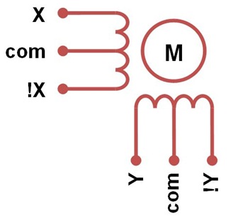 Unipolar stepper motor coils
For the experimenter, one way to distinguish common wire from a coil-end wire is by measuring the resistance. Resistance between common wire and coil-end wire is always half of what it is between coil-end and coil-end wires. This is due to the fact that there is actually twice the length of coil between the ends and only half from center (common wire) to the end. A quick way to determine if the stepper motor is working is to short circuit every two pairs and try turning the shaft, whenever a higher than normal resistance is felt, it indicates that the circuit to the particular winding is closed and that the phase is working.
Unipolar stepper motors with six or eight wires may be driven using bipolar drivers by leaving the phase commons disconnected, and driving the two windings of each phase together. It is also possible to use a bipolar driver to drive only one winding of each phase, leaving half of the windings unused.
Bipolar Motors
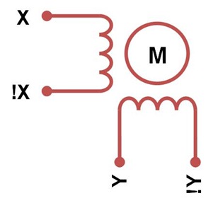
Bipolar motors have logically a single winding per phase. The current in a winding needs to be reversed in order to reverse a magnetic pole, so the driving circuit must be more complicated, typically with an H-bridge arrangement. There are two leads per phase, none are common.
Static friction effects using an H-bridge have been observed with certain drive topologies. Because windings are better utilized, they are more powerful than a unipolar motor of the same weight.
Bipolar stepper motor coils
Unipolar vs. Bipolar
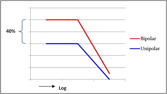
The torque of the stepper motor is proportional to the magnetic field intensity of the stator windings. It may be increased only by adding more windings or by increasing the current. A natural limit against any current increase is the danger of saturating the iron core. Much more important is the maximum temperature rise of the motor, due to the power loss in the stator windings. This shows one advantage of the bipolar circuit, which, compared to unipolar systems, has only half of the copper resistance because of the double cross section of the wire. The winding current may be increased by the factor √2 and this produces a direct proportional affect on the torque. At their power loss limit bipolar motors thus deliver about 40 % more torque (Figure 5) than unipolar motors built on the same frame. If a higher torque is not required, one may either reduce the motor size or the power loss. By comparing Figure 3 and Figure 4, you will notice that a unipolar stepper can be control using bipolar method by removing the connection of the common wires.
Bipolar motors driver deliver more torque than unipolar motors.
Three-Phase and More
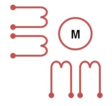
There’s an enquiry posted by a final semester student from INTI International College in Cytron’s website, asking about the methods to differentiate between two-phase and four-phase stepper motors. I hope that you are very familiar with the basic windings of the coils in two-phase stepper motor when you reach here. Figure 6 shows the windings of a three-phase stepper motor. For three-phase bipolar, just eliminate the ‘com’ connection in Figure 6. Without further explains, the differences between two-phase and three-phase stepper motor can be seen clearly. So adding another coil to the diagram in Figure 6 yields a four-phase stepper motor in this case. Until now, you should notice that by observing the number of wires doesn’t guarantee you to determine the type of motor correctly.
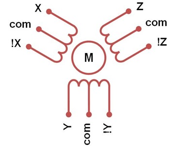 Three-phase unipolar stepper motor coils
8-Lead Stepper Motor
An 8 lead stepper motor is wound like a unipolar stepper, but the leads are not joined to common internally to the motor. This kind of motor can be wired in several configurations:
- 2-phase unipolar with series windings and common wires.
- 2-phase bipolar with series windings and ignore the common wires. This gives higher inductance but lower current per winding.
- 2-phase bipolar with parallel windings. This requires higher current but can perform better as the winding inductance is reduced.
- 4-phase bipolar with a single winding per phase. This method will run the motor on only half the available windings, which will reduce the available low speed torque but require less current.
8-lead stepper motor coils
Conclusion
A stepper motor can be a good choice whenever controlled movement is required. Let us end the article with a summary of Pros and Cons of using stepper motors.
Pros
1. The rotation angle of the motor is proportional to the input pulse.
2. The motor has full torque at standstill (if the windings are energized).
3. Precise positioning and repeatability of movement since good stepper motors have an accuracy of 3-5% of a step and this error is non cumulative from one step to the next.
4. Excellent response to starting/stopping/reversing.
5. Very reliable since there are no contact brushes in the motor. Therefore the life of the motor is simply dependant on the life of the bearing.
6. The motors response to digital input pulses provides open-loop control, making the motor simpler and less costly to control.
7. It is possible to achieve very low speed synchronous rotation with a load that is directly coupled to the shaft.
8. A wide range of rotational speeds can be realized as the speed is proportional to the frequency of the input pulses.
Cons
1. More complicated driving algorithm and motor driver circuit is needed.
2. Resonances can occur if not properly controlled.
3. Not easy to operate at extremely high speeds.
The next part of this article will describe the stepper motors driving methods and hardware design. Please stay tuned!
Information taken from:
 International
 Singapore
 Malaysia
 Thailand
 Vietnam
