Your shopping cart is empty!
PROJECT 9
ANALOG SENSOR: LIGHT DETECTION USING LDR
| Back to Project 8 | Go to Project 10 |
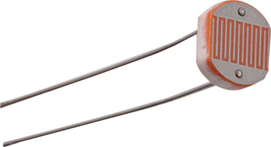
A photoresistor or light dependent resistor (LDR) is a resistor whose resistance decreases with increasing incident light intensity. It can also be referred to as a photoconductor. In here, we going to do a simple connection of LDR and display the ADC and Voltage value on LCD.
———————————————————————————————————————————————————-
COMPONENTS NEEDED
———————————————————————————————————————————————————-
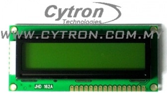 | 16 x 2 LCD Display |
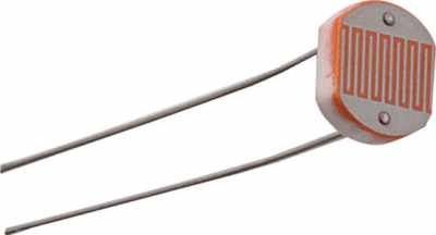 | LIGHT DEPENDENT RESISTOR |
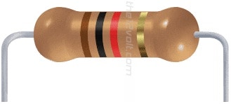 | 1K RESISTOR |
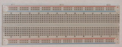 | BREADBOARD |
 | JUMPER WIRES |
———————————————————————————————————————————————————-
CONNECTION
———————————————————————————————————————————————————-
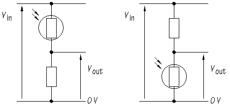
There are 2 ways of constructing the voltage divider which are LDR on top or LDR on bottom.
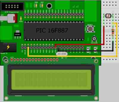
LDR ON TOP
Refer to the figure below, a total of 3 wires are used. The RED wire connects the LDR and VDD. The BLACK connects the resistor and GND. Lastly, the YELLOW wire connects the RA0 and the LCD and resistor. Please refer to this webpage for further details.
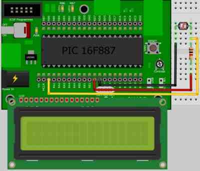
LDR ON BOTTOM
Refer to the figure below, a total of 3 wires are used. The BLACK wire connects between the LDR and VDD. The RED wire connects the resistor and GND. Lastly, YELLOW wire connects the RA0 and the LCD and resistor. Please refer to this webpage for further details.
———————————————————————————————————————————————————-
ADDITIONAL INFORMATION
———————————————————————————————————————————————————-
MEASURING RESISTANCE OF LDR
To measure the LDR resistance, just probe directly the +ve to one side of LDR and the -ve to the other side of LDR.
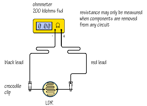
LDR VOUT MEASUREMENT

In this case, we give the Vin as 5V and resistor are 1K.
E.g-1: LDR on Top, Rtop = 10K
Vout = 1K x 5V
1K + 10K
= 0.45V
E.g-2: LDR on bottom, Rbottom= 10K
Vout = 10K x 5V
10K + 1K<
= 4.54V
———————————————————————————————————————————————————-
CODE OVERVIEW
———————————————————————————————————————————————————-
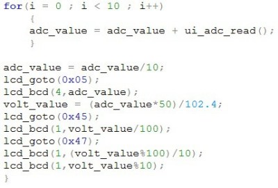
for (i=0 ; i<10 ; i++)
{
adc_value = adc_value + ui_adc_read();
}
Read and store the ourput value of ADC for 10 times.
adc_value = adc_value/10;
Divide the adc_value by 10 times to get the average result.
volt_value = (adc_value*50)/102.4;
Same as project_4, to display the output in voltage, we need to recalculate the adc_value given and times with 50 and divided by 102.4.
| Back to Project 8 | Go to Project 10 |
———————————————————————————————————————————————————-
 International
 Singapore
 Malaysia
 Thailand
 Vietnam
