Your shopping cart is empty!
For this project, we will discover how to manage a digital input signal. As we know that digital signal is either HIGH (1) and LOW (0) only. But for different integrated circuit such as PIC MCU, we need to define at the beginning of the code that the port using are either input or output and also declaration for digital or analog signal send and received.
COMPONENT NEEDED
 | PUSH BUTTON & LEDS ON SK40C |
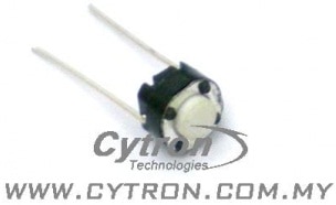 | PUSH BUTTON |
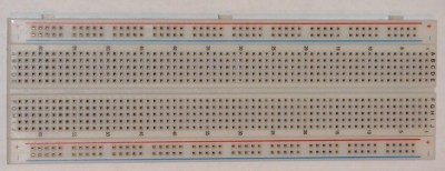 | BREADBAORD |
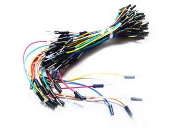 | JUMPER WIRES |
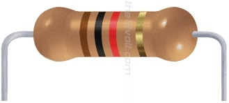 | 1K RESISTOR |
CONNECTION
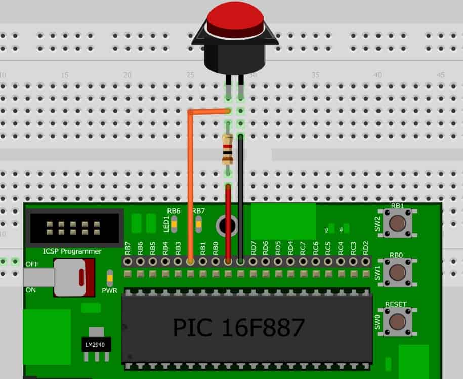
There is no need to connect extra push button to SK40C board because inside SK40C, there is already have 2 push button on board which is purposely prepared for user to use it. These push button are already connected to RB0 and RB1 while external push button are connected to RB2. So all we need to do is just declare there 3 port as INPUT. As for the output, we use the on board LEDs to show us that we have push the push button. The LEDs are connect to RB6 and RB7. To use the LEDs, we need to declare it as an OUTPUT.
ADDITIONAL INFORMATION
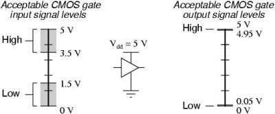
Besides on using the push button on SK40C, we can use others component to replace it such as limit switch, keypad and etc. Referring to the figure below, input signal read at HIGH are between 3.5V to 5V and while LOW are read between 1.5V to 0V. For output of the external device are giving the digital value of HIGH at between 4.95V to 5V and LOW at between 0.05V to 0V. As long as the logic input and output voltage are within this level, the PIC MCU can read it without any conversion. For more information, please refer to this webpage.
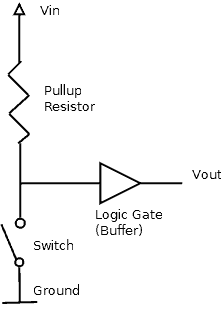
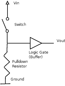
On the other hand, by adding an additional switch to the PIC16F887, the switch have to be pull-up due to the some port are not have this pull-up function and it may effect out coding if we are reading the push button I/O. Besides on pull-up resistor, there are also an pull-down resistor such as showing in picture below.
In this project, we are using one additional push button so it may need to be pull-up like the picture showing. For more information about pull up resistor. Please refer to this webpage.
CODE OVERVIEW
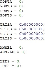
PORTA = 0;
To prevent the data latch, we clear PORTA so that it won’t affect Tri-State Register (TRIS).
TRISB = 0b00000111;
Push buttons is connected to RB0 to RB2. To make in as an input, we have set HIGH(1) to TRISB.0, TRISB.1 and TRISB.2. The rest are declare as an output port.
ANSEL = 0;
ANSEL is an analog select high register for PORTA. LOW(0) the register will make it DIGITAL I/O while HIGH(1) it will make it an ANALOG I/O.
ANSELH = 0;
ANSELH is an analog select high register for PORTB. LOW(0) the register will make it DIGITAL I/O while HIGH(1) it will make it an ANALOG I/O.
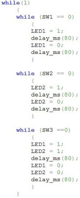
while (SW1 == 0)
Check whether the switch 1 is LOW(0). If it does then do the following code which is blink the LED1 and loop forever. The symbol == is usually use to represent the signal in digital. While = is usually use to represent the signal in analog.
 International
 Singapore
 Malaysia
 Thailand
 Vietnam
