4x4x4 LED Cube using Arduino UNO without extra IC

4x4x4 LED Cube using Arduino UNO without extra IC

INTRODUCTION

Good day,

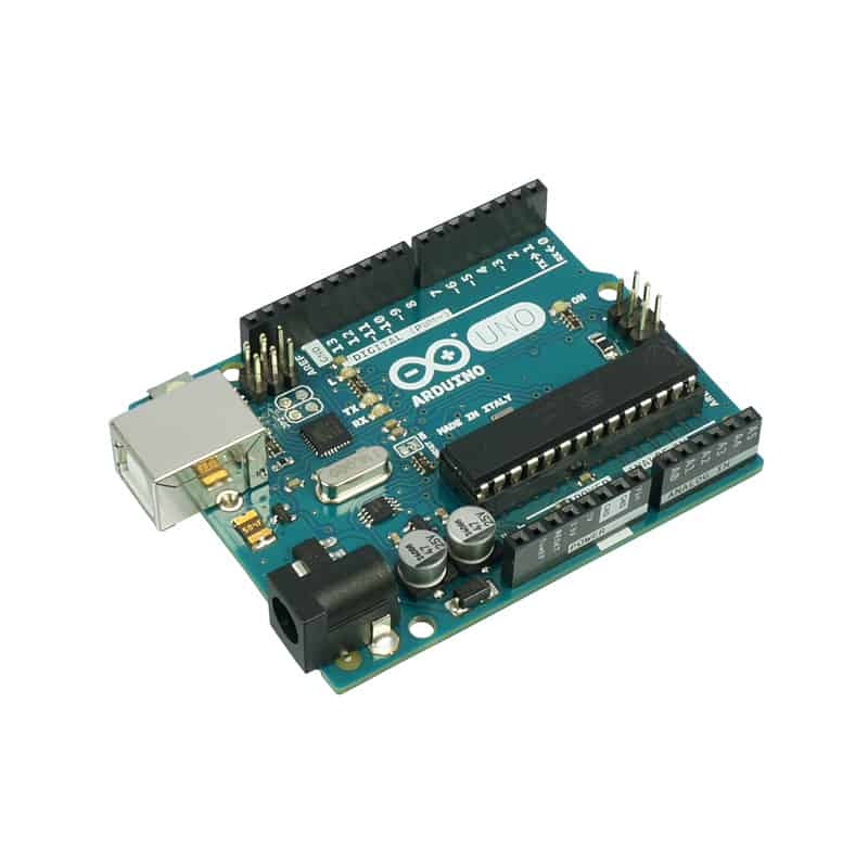
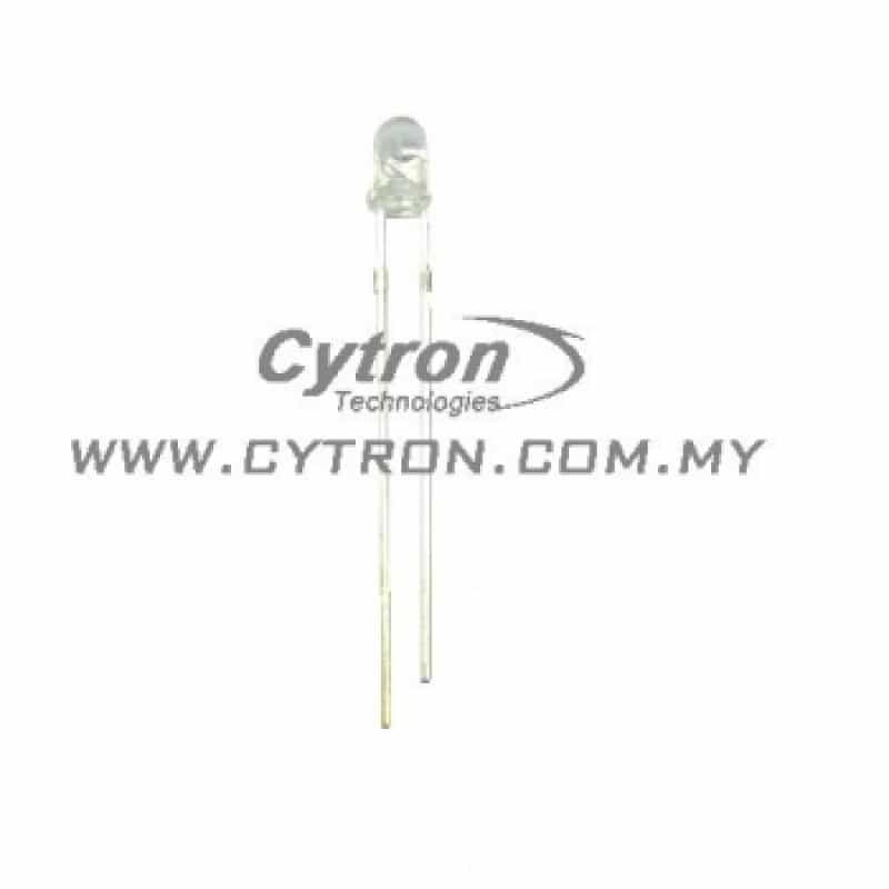
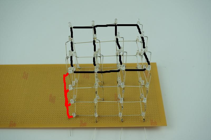
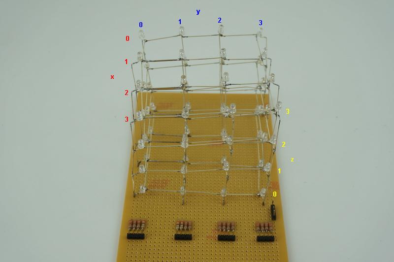
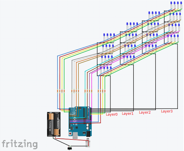
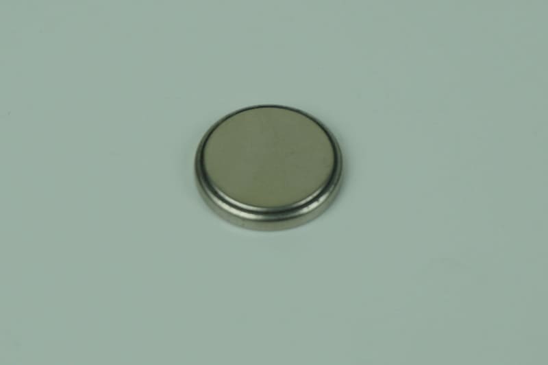
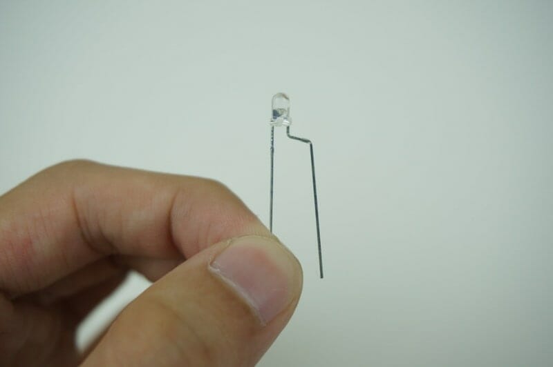
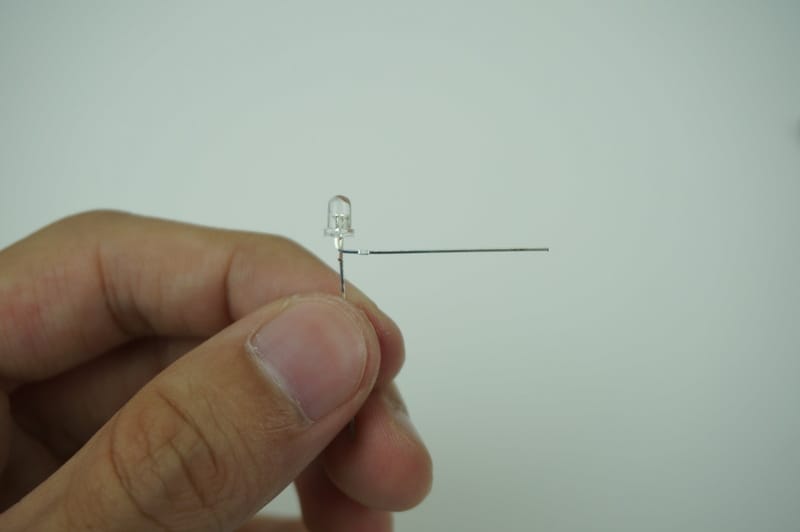
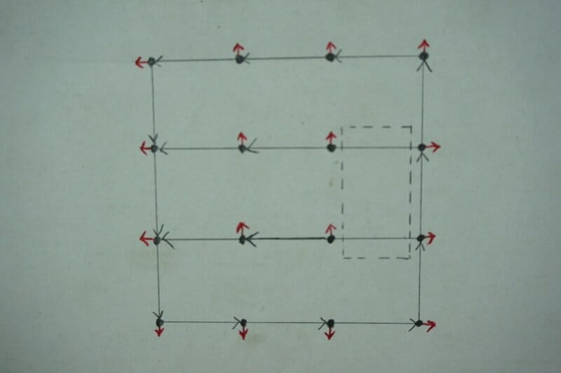
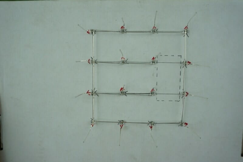
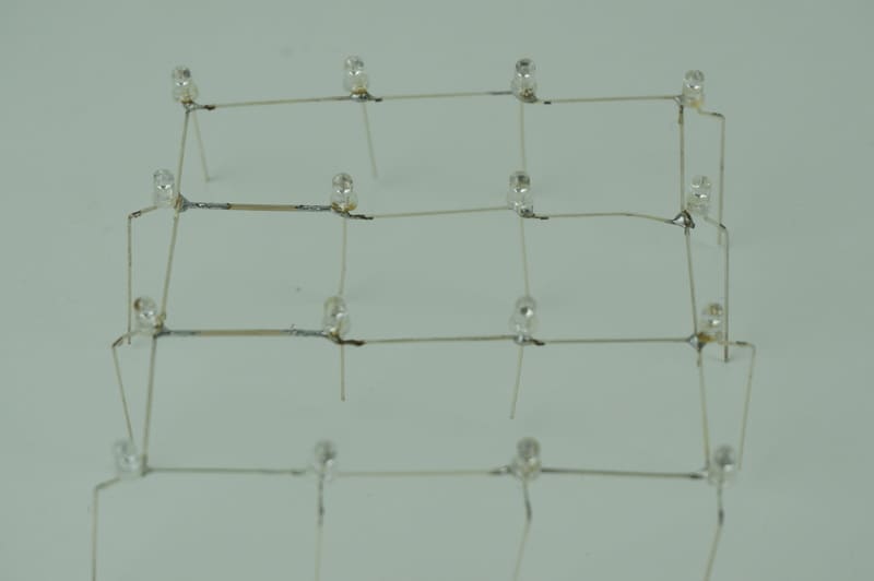
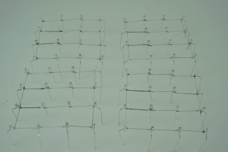
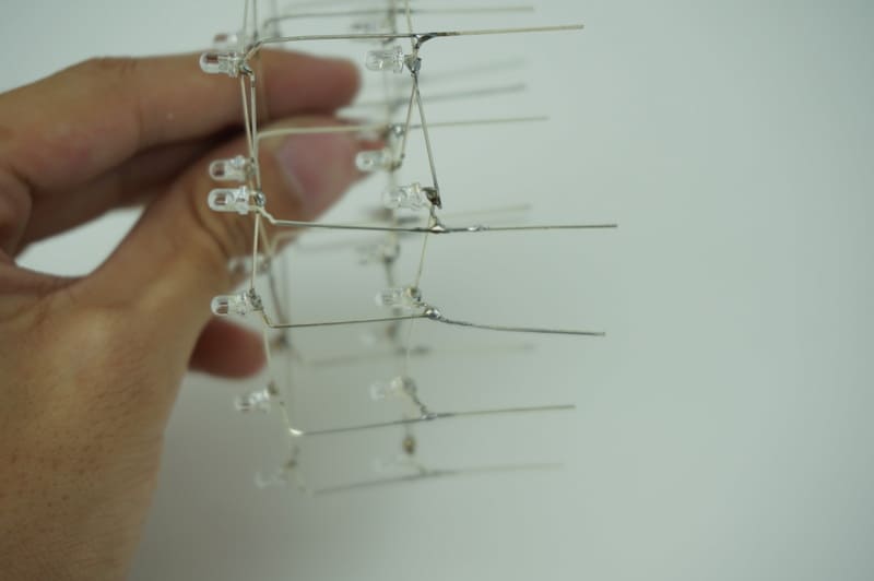
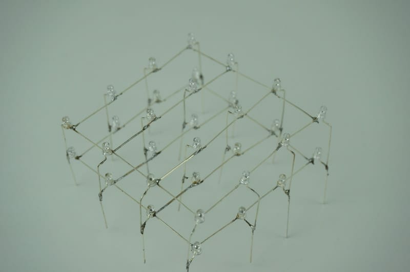
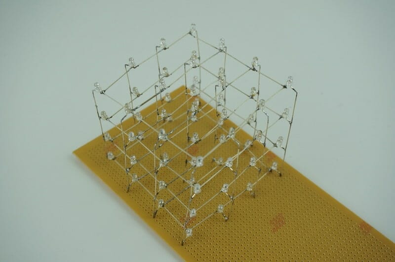
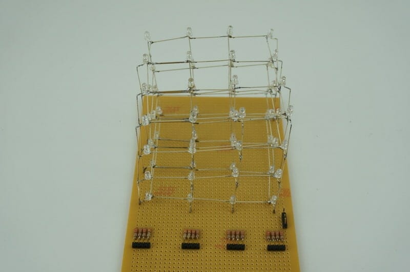
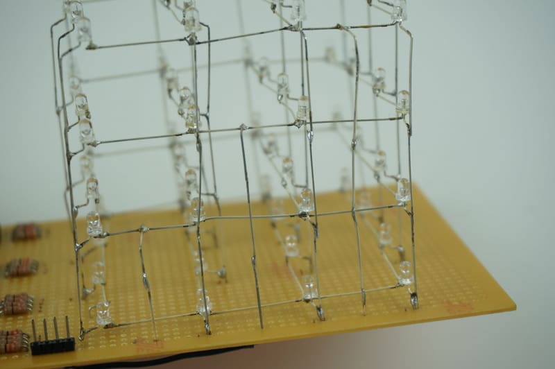
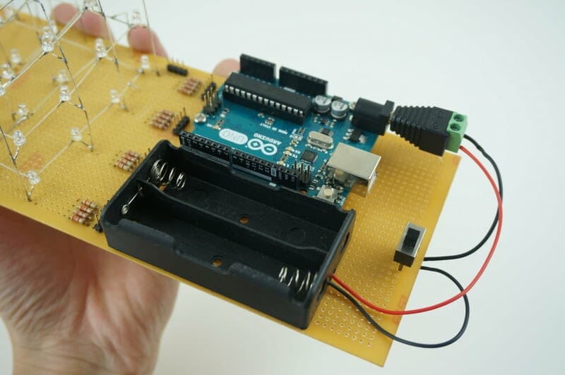
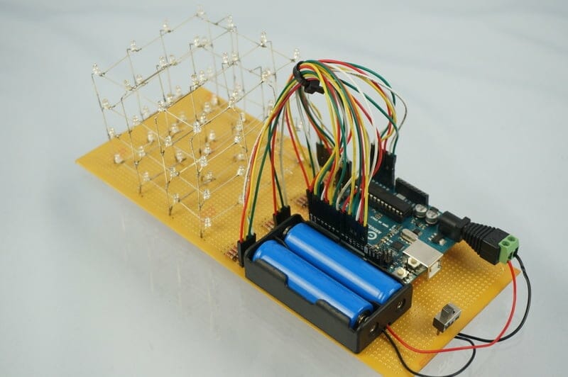
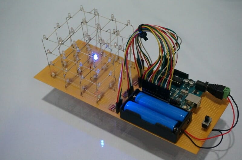
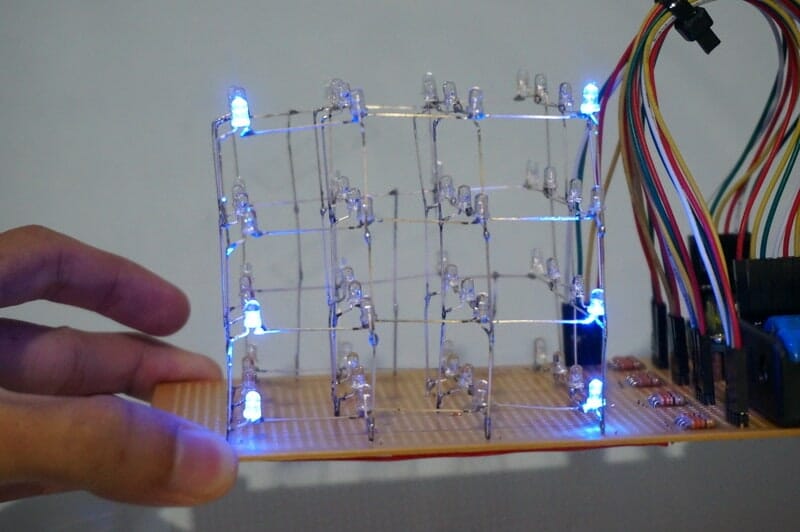
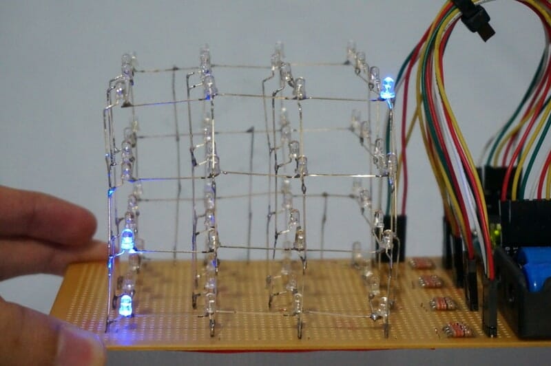
As we all know, an LED Cube is a bunch of LED that arranged in a cube shape that can perform some interesting lighting effects according to your program. In this tutorial, we are going to learn how to construct a 4x4x4 LED Cube using Arduino UNO board without any extra IC, solely with the available on-board pins. for further inquiries please go to our technical forum as we seldom check the comment section of tutorial.  


PREPARATION

Hardware:

Software:

Arduino IDE – an open source Integrated Development Environment used to program Arduino board. You can download it here.

P/S: Actually, we only need 64 of LEDs. I stated 70 LEDs so there will be extra LEDs in case anything goes wrong.

You also need to have good soldering skills. If you are a newbie in soldering, try to get used to it before you can start to soldering the cube.


ADDITIONAL INFORMATION

Before we start developing the cube, there are some terminologies on the words that will be used in this tutorial.

Refer to the image below:

  • LAYER(black color line in picture)
    • The cathode (negative/shorter) legs are all connected in the same horizontal plane.
  • LINE (red color line in picture)
    • The anode (positive/longer) legs are all connected in same vertical position.

(Click the image for larger view and please do not complain my drawing, I tried my best =.=|||)

Now, let’s give each line and layer a name so that we can easily find it.

From the picture above, there are 3 axes namely x,y, and z.

  • xy-plane represent the layout of horizontal layer
  • z-axis represent the vertical height of layers.

The table below show the representation of XYZ coordinates.

XYZ coordinaterepresentation
xy[0][0]line at the top left
xy[0][3]line at the top right
xy[3][0]line at the bottom left
xy[3][3]line at the bottom right
z[0]lowest layer
z[3]top layer
xyz[3][3][3]particular LED(bottom right line, top layer.)
 

CIRCUIT DIAGRAM

The circuit will looks a little bit complicated, so I have attached the Fritzing file along with the source code in case you want to have a better looks. You can download it at the attachment below.


PREPARATION

Alright, the very first step in developing an LED cube is to make sure that every LED is working (not joking, every!). You can test it using a 3V cell battery, as shown in pictures at the left. Make sure to check the polarities of cell battery first, or else your LED won’t work.

Next, to get a nice cube shape, we need to do something to the LED legs. Bend the anode leg of LED as shown.

After that, bend the cathode leg to 90° as shown. You can bend to any direction, but just be sure that the direction is consistent. If you are not sure where to bend, just follow my direction.

Alright, finish with LED. Now we want something that can help us hold the LEDs while we solder, and keep all LEDs in shape.

Get a box or anything else that you could pokes a hole on it, draw something like the picture shown at the left. The distance between each nodes would be approximately 2.5cm (the length of LED cathode leg).

(Click the image for larger view)

Notice I drew a dashed rectangle portion there, we will get to it in next step.

Poke all 16 nodes on the holder, and place LED on it. Arrange your LEDs as the arrow indicated, black arrow represents the cathode, red arrow represents the anode.

After the arrangement, you will see that there is no leg connection inside the dashed portion, this is not a problem, as we already connected all cathode legs.

(Click the image for larger view)

Now, get your solder gun ready, solder the negative legs that touching each other so that all cathodes are connected as a layer.

Out of obsession, I soldered a lead pin to the dashed region to make the layer more comfortable to look at.

Then, take some rest, and start another one. Repeat this step until you have 4 layers =P.

So, finished with all 4 layers? Then, combine layer with layer, it is very hard to do it alone, so you have to find a friend (or victim? :-P) to help you hold both layers together while you do the soldering. A reminder to your friend, it gets really hot…

After finish stacking all 4 layers, mount your cube on a donut board, and bend the LED legs to fix it.

Solder and trim the extra portion of legs.

Next, putting resistors and pin headers on the board as shown, and solder each resistor to one pin. Trim the extra portion of resistor’s leg.

Solder each LED leg to corresponding resistor, take extra care on the position to avoid any confusion. The connection is soldered exactly the same as in Fritzing file, and I also clarify it in the source code too.

Add a conductor to each layer and solder it to the corresponding pin header so that we can connect to Arduino board.

I trimmed some broken LED legs for this purpose, you can just use a wire if you want.

Alright, now mounting Arduino board and battery holder on the donut board, and add a switch between them. The switch is optional, but it helps you from frequently plug and unplug the DC jack.

Finally, we have arrived at the last step in constructing an LED cube, connect all pin headers to the Arduino board using male-to-female jumper wires, make sure to connect it as shown in the Fritzing diagram, or else the code might go wrong. You can tidy up the jumper wires using a cable tie.

I am sure that someone will find suspicious here. Yes, you see it right, I am connecting my wires to Arduino analog input pin. If you want to ask why, it is because the analog pins can also act as general purpose I/O (GPIO) too. This is not something magical and it is stated in Arduino official website here. So with this feature, it allow us to control 4x4x4 LED cube using Arduino UNO board without I/O expansion IC.

In the end, your cube should looks something like this:


CODE OVERVIEW

So we have successfully built an LED cube, the next thing is to understand how the cube works.

Suppose we want the LED at xyz[3][0][3] light up as the image below. What we need to do is just apply HIGH to the pin at xy[3][0], and LOW to the pin at z[3], simple and understandable.

Now, what if I want the LED at xyz[0][0][0] to light up too? You might think just simply apply HIGH to the pin at xy[0][0] and LOW the z[0]. However, the result will looks like this:

You will notice xyz[0][0][3], and xyz[3][0][0] also lighted up.

(P/S: Layer1 is not lighted up, it is purely the reflection from layer0)

Why? This is because when you turn on xyz[0][0][0], line xy[3][0] is still HIGH. So when you turn z[0] to LOW, the circuit for xyz[3][0][0] is also completed thus it will light up. The same case also apply to xyz[0][0][3]. Since z[3] is originally LOW, applying HIGH to line xy[0][0] will turn it on too.

Does it have a solution? Of course. A method called multiplexing is quite simple. Just repeatedly turning on one LED while the others are off, then reverse the situation quickly, and ta-daa!!  :

(P/S: layer1 is not lighted up, it is purely the reflection from layer0)

Again, this is not something magical. It is just the Arduino board switches between these two LEDs faster than human eyes could detect, thus creating an optical illusion of two LEDs light up at the same time.

Now, let’s see the code that have been provided. There are four additional function for you to call.

I will go through it one by one.

This function is used to clear all LEDs, returning them to their default state: LOW for lines, and HIGH for layers.

It takes no parameter and return nothing, so you can just use it by calling

cubeClear();

This function will turns on all LEDs, it takes no parameter and return nothing, so just call it by

cubeON();