Arduino + PS2 shield + MDDS10 for mobile robot control

Arduino + PS2 shield + MDDS10 for mobile robot control

INTRODUCTION


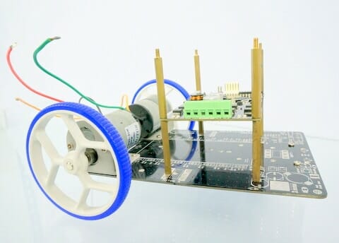
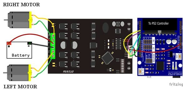
Ever wanted to build a simple mobile robot that can be controlled by a wireless PS2 controller? Think it’s too difficult for you? Well, think about it again. Because it’s actually easy and straight forward. In this tutorial, I will show you how to build the robot step by step.


HARDWARE REQUIRED


Lets start to build the body for the mobile robot. You can design it with your own creativity, but you need to have all 8 important items below to build the mobile robot. Please make sure your robot is stable. 


STEP BY STEP PREPARATION


First, I setup the robot base and a pair of DC geared motor together. To make it stable, I put the ball caster at the front base. After that I attached the MDDS10 at the top of the base.

As you can see in the figure, there is a DIP switch in red box. The DIP switch is to choose the input mode for the MDDS10. For this robot, I choose to set the MDDS10 to PWM input mode with microcontroller (both independent). So, I have to set the DIP switch1, switch3, switch4 and switch6 to 1. Others remain 0. (Up is 1 and down is 0).

After setting the DIP switch, connect the motor to the motor port. Connect your motor according to its position. Left motor to the left port and right motor to the right port. Between the left and right port, there is power source port. Please connect the power source according to the polarity.There is no polarity protection for this MDDS10 board, so please be extra cautious!!

The PS2 shield board consist of receiver(RX), transmitter(TX) and baudrate for UART communication. Based on the picture, I have set the TX to D3, RX to D2 and for the baudrate, I set it to 9.6K. All this configuration can be done by placing the jumper to the desired position. Please make sure that you download the library for the PS2 shield here and update your Arduino library.


CIRCUIT DIAGRAM


Now, I will show you how to connect the MDDS10 to PS2 shield. But before that, you have to stack the PS2 shield on CT UNO.  And configures some of the pins for communication pin.

  • DIG1 pin (MDDS10) connect to Digital pin 7 (Shield-PS2)
  • DIG2 pin connect to Digital pin 4
  • AN1 pin to Digital pin 6
  • AN2 pin to Digital pin 5 
  • +5V to 5V CT-UNO
  • GND to GND CT UNO

Now I have completed the hardware setup of my robot. Next, I will explain on the software.


CODE OVERVIEW


In this sample source code, I just use Left joystick and Left2 button. If Left2 button is pushed, it will go Acceleration(); function. In the Acceleration() function, the speed is higher compared to Normal() function.

void loop()
{
//joystick value
ly=ps2.readButton(PS2_JOYSTICK_LEFT_Y_AXIS);
lx=ps2.readButton(PS2_JOYSTICK_LEFT_X_AXIS);
acc=(ps2.readButton(PS2_LEFT_2) == 0);
if(acc==HIGH)
{ Normal();}
else
{ Acceleration();}
Movement();
}

VIDEO


In English:

In Malay language

Thank you for reading and watching the video. I hope you understand my tutorial. 

ATTACHMENT


BUY